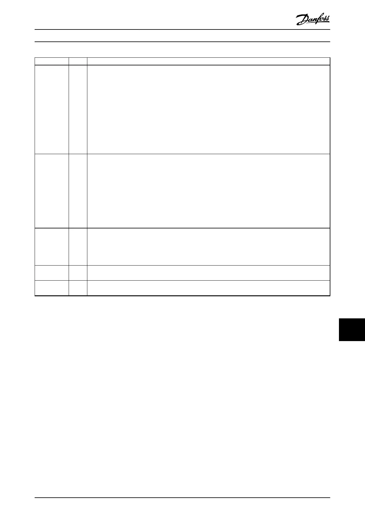
Description Pos Possible option
Mains option 21 X: No mains option
3: Mains disconnect and fuse
5: Mains disconnect, fuse, and load sharing
7: Fuse
A: Fuse and load sharing
D: Load sharing
E: Mains disconnect, contactor, and fuses
F: Mains circuit breaker, contactor, and fuses
G: Mains disconnect, contactor, load sharing terminals, and fuses
H: Mains circuit breaker, contactor, load sharing terminals, and fuses
J: Mains circuit breaker and fuses
K: Mains circuit breaker, load sharing terminals, and fuses
Power
terminals &
motor starters
22 X: No option
E 30 A, fuse-protected power terminals
F: 30 A, fuse-protected power terminals and 2.5–4 A manual motor starter
G: 30 A, fuse-protected power terminals and 4–6.3 A manual motor starter
H: 30 A, fuse-protected power terminals and 6.3–10 A manual motor starter
J: 30 A, fuse-protected power terminals and 10–16 A manual motor starter
K: Two 2.5–4 A manual motor starters
L: Two 4–6.3 A manual motor starters
M: Two 6.3–10 A manual motor starters
N: Two 10–16 A manual motor starters
Auxiliary 24 V
supply &
external
temperature
monitoring
23 X: No option
H: 5 A, 24 V supply (customer use)
J: External temperature monitoring
G: 5 A, 24 V supply (customer use) and external temperature monitoring
Software
release
24–27 Actual software
Software
language
28 X: Standard language pack
Table 13.4 Ordering Type Code for Enclosures F1–F4 and F8–F13
2)
1) Requires VLT
®
PTC Thermistor Card MCB 112 and VLT
®
Extended Relay Card MCB 113.
How to Order a Drive Design Guide
MG16C302 Danfoss A/S © 11/2017 All rights reserved. 219
13 13
 Loading...


