‒
the supply voltage exceeds 36 V
‒
the supply voltage falls below 8.5 V
‒
the internal clock frequency fails
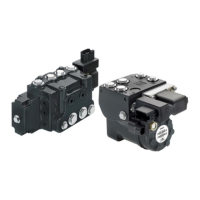
PVE-EX fault monitoring
Fault monitoring overview
PVE type PVEH/PVES-U
versions
PVES versions PVEO versions
Fault monitoring Active Passive No
Delay before error out 500 ms 250 ms —
Closed loop deactivated memory (reset needed) Yes No —
Error mode
No fault Error output status – Low
Fault output on PVE: < 2 V
—
Input signal fault
Transducer (LVDT)
Close loop fault
Error output status – High
Fault output on PVE: U
DC
—
Caution
The installation must be performed as intended in order to have a safe system.
Please refer to the information in this manual for an assistance, or consult with a professional.
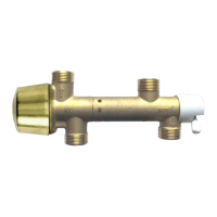
Direction indication feedback (-DI)
PVE with build in indication for spool movement direction are available.
The PVE–DI has dual power supply. U
DC1
only supplies solenoid valves. U
DC2
supplies electronics and feed
back. The PVE does not work without U
DC2
. DI-A and DI-B are relative standard mounting. The input
signal fault monitoring is disabled if U
DC1
is disabled. DI-A and DI-B are relative standard mounting.
The DI has two direction feeedback signals with output high (close to U
DC
) when the spool is in neutral
position. If the spool moves out of neutral position, the direction signal switches to low (< 0.2 V). One of
the signals goes low by spool ~0.8 mm out of neutral and high by spool within 0,4 mm out of neutral.
Both direction indication signals go low when the error indicator goes high.
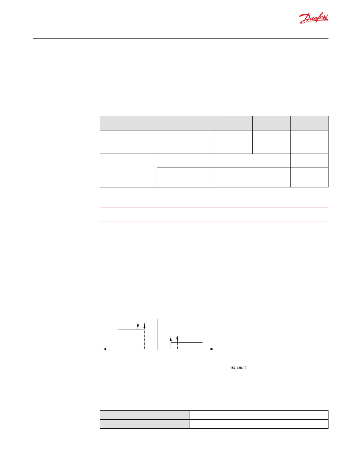
Direction indication feedback
DI-A low
DI-B high
DI-A high
DI-B low
Spool position ‘x’
mm [in]
B-port
PVBS away from PVE
A-port
PVBS towards PVE
0.4 0.8-0.8 -0.4 0
As shown in the figure, both “DI-A” and “DI-B” signals are “High” when the spool is in neutral position.
When the spool is moving in the A direction, the “DI-A” signal goes “Low” and the “DI-B” signal stays
“High”. The reverse is true when the spool is moved in the B direction.
Values for Direction Indicators (-DI)
Transition from high to low
0.8 ± 1 mm [0.031 in]
Transition from low to high
0.4 ± 1 mm [0.015 in]
Technical Information
Electrohydraulic Actuators PVE-EX
Safety and monitoring
©
Danfoss | October 2017 BC00000393en-US0102 | 23
 Loading...