Chapter 6 Fault diagnosis and solutions VFD500 high performance vector control frequency inverter user manual
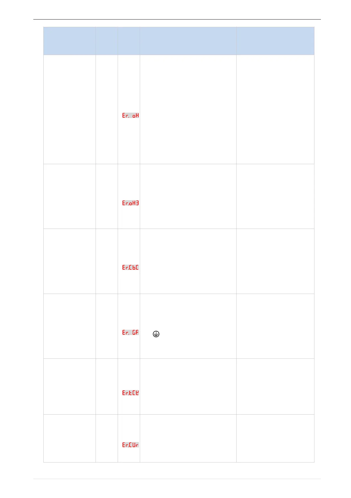
1: The ambient temperature is
too
high.
2: The air filter is blocked.
3: The fan is damaged.
4: The thermally sensitive
resistor of
the IGBT module is damaged.
5: The inverter IGBT module is
damaged
1:Lower the ambient
temperature.
2: Clean the air filter.
3: Replace thedamaged
fan.
4:Replace the damaged
thermally
sensitive resistor.
5: Replace the inverter
module.
1:The temperature sensor wiring
is loose
2:The motor temperature is too
high
3:Themotor temperature sensor
detects that the temperature is
greater than the set threshold.
1:check the temperature
sensor wiring
2:Improve the carrier
frequency, strengthen the
heat dissipation of the
motor, reduce the load,
and select a motor with
higher power.
3 : C h e c k i f t h e s e t
By wave
current
limitingfault
1: The load is too heavy or
locked-
rotor occurs on the motor.
2: The frequency inverter model
is of
too small power class
1: Reduce the load and
check
the motor and mechanical
condition.
2: Select a frequency
inverter of
higher power class.
1. Confirm the insulation
resistance of the motor. If
it is turned on, replace the
motor.
2. Check the power cable
of the motor to eliminate
the fault point.
3, reduce the carrier
frequency, install the
output reactor
module
temperature
detection fault
1, Temperature detection line
broken
2, Drive board is faulty
3. Main control board is faulty
4, The environmental
temperature is too low
1. Check the thermistor
wiring
2. Ask for technical
support
3. Ask for technical
support
4, manual intervention to
drive the temperature rise
1: The HALL device is faulty.
2: The drive board is faulty.
3: The control board is faulty
1: Replace the faulty
HALL
device.
2: Replace the faulty
drive board.
3: Ask for technical
support.
1. Motor burnout or insulation
aging
2, The cable is damaged and
contact, short circuit
3. The distributed capacitance of
the terminal and motor cable
is larger
motor cable
4, Hardware is damaged
 Loading...

