VLT
®
6000 HVAC
100
★ = factory setting. ( ) = display text [ ] = value for use in communication via serial communication port
MG.60.B1.02 - VLT is a registered Danfoss trade mark
■■
■■
■ Analogue inputs
Two analogue inputs for voltage signals (terminals 53
and 54) are provided for reference and feedback
signals. Furthermore, an analogue input is available
for a current signal (terminal 60). A thermistor can be
connected to voltage input 53 or 54.
The two analogue voltage inputs can be scaled in the
range of 0-10 V DC; the current input in the range of
0-20 mA.
The table below gives the possibilities for
programming the analogue inputs.
Parameter 317 Time out and 318 Function after time
out allow activation of a time-out function on all
analogue inputs. If the signal value of the reference or
feedback signal connected to one of the analogue
input terminals drops to below 50% of the minimum
scaling, a function will be activated after the time out
determined in parameter 318, Function after time out.
Analogue inputs terminal no. 53(voltage) 54(voltage) 60(current)
parameter 308 311 314
308 Terminal 53, analogue input voltage
(AI [V] 53 FUNCT.)
Value:
No operation (NO OPERATION) [0] [0] ★ [0]
Reference (REFERENCE [1] ★ [1] [1] ★
Feedback (FEEDBACK) [2] [2] [2]
Thermistor (THERMISTOR) [3] [3]
Function:
This parameter is used to select the required function
to be linked to terminal 53.
Description of choice:
No operation.No operation.
No operation.No operation.
No operation. Is selected if the VLT frequency con-
verter is not to react to signals connected to the
terminal.
ReferenceReference
ReferenceReference
Reference
..
..
. Is selected to enable change of reference
by means of an analogue reference signal.
If reference signals are connected to several inputs,
these reference signals must be added up.
Feedback.Feedback.
Feedback.Feedback.
Feedback. If a feedback signal in connected, there is
a choice of a voltage input (terminal 53 or 54) or a
current input (terminal 60) as feedback. In the case of
zone regulation, feedback signals must be selected as
voltage inputs (terminals 53 and 54).
See Feedback handling on page 115.
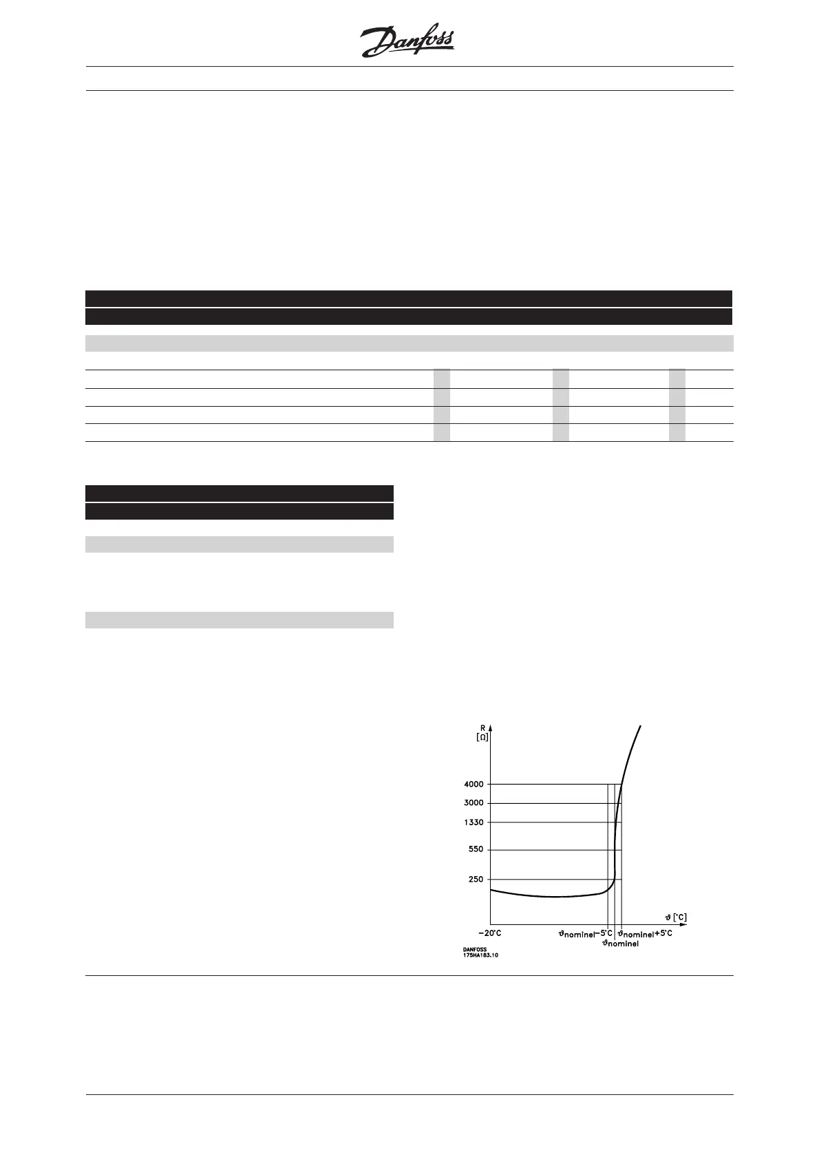
ThermistorThermistor
ThermistorThermistor
Thermistor
..
..
. Is selected if a thermistor integrated in
the motor is to be able to stop the VLT frequency
converter in case of motor overtemperature. The cut-
out value is 3 kohm.
If a motor features a Klixon thermal switch instead,
this can also be connected to the input. If motors run
in parallel, the thermistors/thermal switches can be
connected in series (total resistance < 3 kohm).
Parameter 117 Motor thermal protection must be
programmed for Thermal warning [1] or Thermistor
trip [2], and the thermistor must be inserted between
terminal 53 or 54 (analogue voltage input) and
terminal 50 (+10 V supply).

 Loading...


