VLT
®
6000 HVAC
106
★ = factory setting. ( ) = display text [ ] = value for use in communication via serial communication port
MG.60.B1.02 - VLT is a registered Danfoss trade mark
Relay outputs Relay no. 1 2
parameter 323 326
Value:
No function (NO FUNCTION) [0] [0]
Ready signal (READY) [1] [1]
Standby (STAND BY) [2] [2]
Running (RUNNING) [3] ★ [3]
Running at ref. value (RUNNING AT REFERENCE) [4] [4]
Running, no warning (RUNNING NO WARNING) [5] [5]
Local reference active (DRIVE IN LOCAL REF) [6] [6]
Remote references active (DRIVE IN REMOTE REF.) [7] [7]
Alarm (ALARM) ★ [8] [8]
Alarm or warning (ALARM OR WARNING) [9] [9]
No alarm (NO ALARM) [10] [10]
Current limit (CURRENT LIMIT) [11] [11]
Safety interlock (SAFETY INTERLOCK) [12] [12]
Start command active (START SIGNAL APPLIED) [13] [13]
Reversing (RUNNING IN REVERSE) [14] [14]
Thermal warning (THERMAL WARNING) [15] [15]
Hand mode active (DRIVE IN HAND MODE) [16] [16]
Auto mode active (DRIVE IN AUTO MODE) [17] [17]
Sleep mode (SLEEP MODE) [18] [18]
Output frequency lower than f
LOW
parameter 223 (F OUT < F LOW) [19] [19]
Output frequency higher than f
HIGH
parameter 224 (F OUT > F HIGH) [20] [20]
Out of frequency range (FREQ RANGE WARN.) [21] [21]
Output current lower than I
LOW
parameter 221 (I OUT < I LOW) [22] [22]
Output current higher than I
HIGH
parameter 222 (I OUT > I HIGH) [23] [23]
Out of current range (CURRENT RANGE WARN.) [24] [24]
Out of feedback range (FEEDBACK RANGE WARN.) [25] [25]
Out of reference range (REFERENCE RANGE WARN.) [26] [26]
Relay 123 (RELAY 123) [27] [27]
Mains fault (MAINS PHASE LOSS) [28] [28]
Control word 11/12 (CONTROL WORD 11/12) [29] [29]
■■
■■
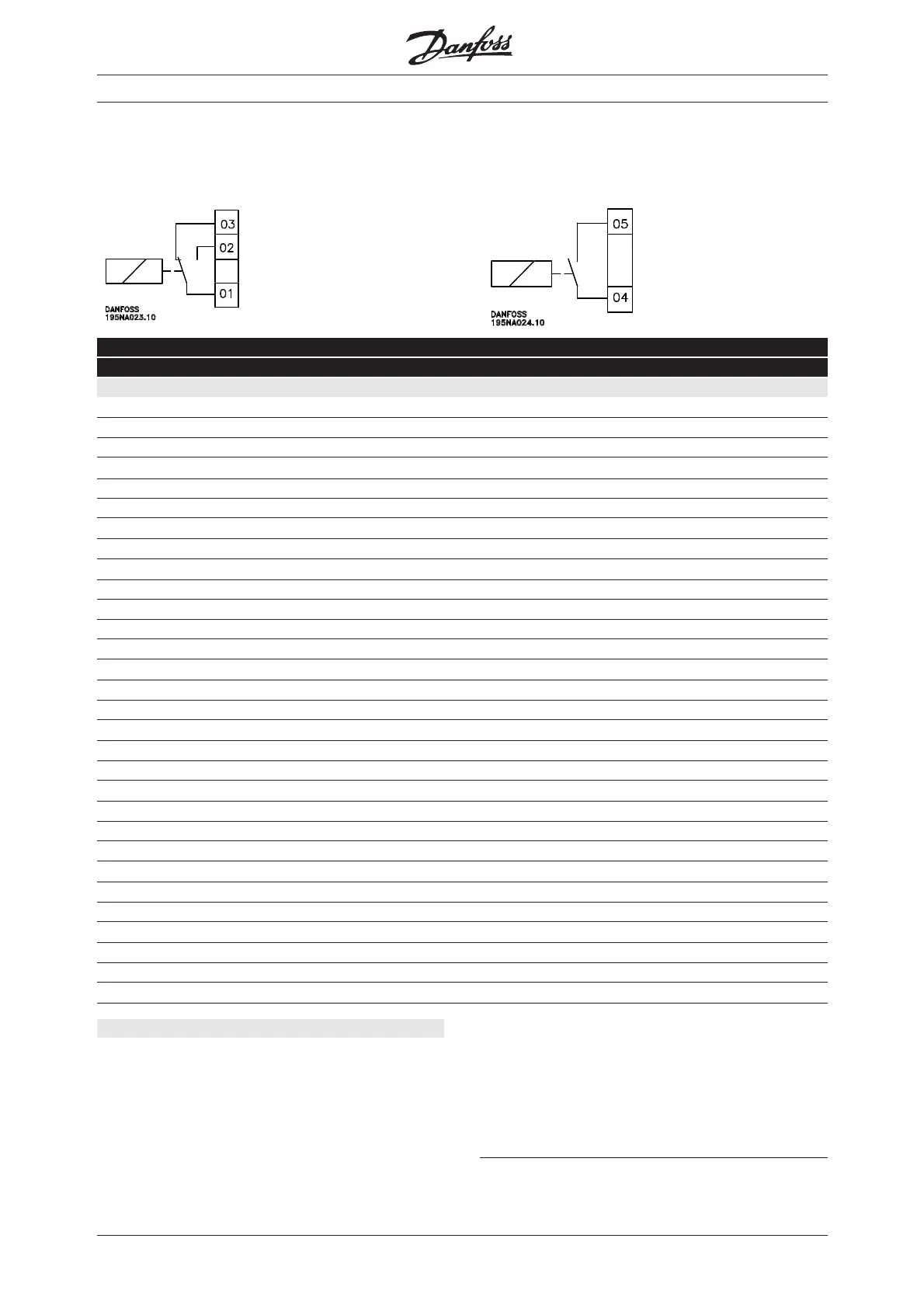
■ Relay outputs
Relay outputs 1 and 2 can be used to give the
present status or a warning.
Relay 1
1 - 3 break, 1 - 2 make
Max. 240 V AC, 2 Amp.
The relay is placed with the
mains and motor terminals.
Relay 2
4 - 5 make
Max. 50 V AC, 1 A, 60 VA.
Max. 75 V DC, 1 A, 30 W.
The relay is placed on the
control card, see page 65.
Description of choice:
See description of [0] - [28] on page 104.
Control word bit 11/12Control word bit 11/12
Control word bit 11/12Control word bit 11/12
Control word bit 11/12, relay 1 and relay 2 can be
activated via the serial communication. Bit 11
activates relay 1 and bit 12 activates relay 2.
If the parameter 556 Bus time interval function
becomes active, relay 1 and relay 2 will become cut off
if they are activated via the serial communication.
See paragraph Serial communication in Design Guide.

 Loading...


