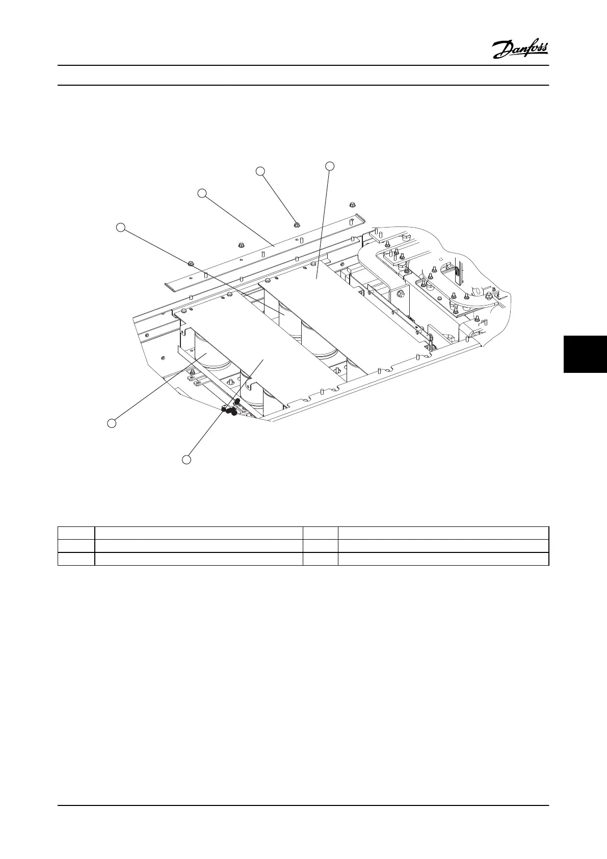
8.3.4 Upper Capacitor Bank Assembly
1
2
3
4
5
6
H1
K0070
H2
H
X2
F
X 1
130BX410
Figure 8.10 Upper Capacitor Bank Assembly
1
Upper capacitor bank 4 Upper capacitor bank cover plate
2 Input terminal mounting plate support bracket 5 Lower capacitor bank cover plate
3 Retaining nut (0.39 in [10 mm]) 6 Lower capacitor bank
Table 8.10
1. Remove the input terminal mounting plate in
accordance with the procedure.
2. Remove the input terminal mounting plate
support bracket by removing four nuts (0.39 in
[10 mm]).
3. The capacitor bank connection to the DC bus
bars can be seen recessed in the gap between
the upper and lower capacitor banks. A minimum
extension of 6 in [150 mm] is required. Remove
the 6 electrical connection nuts (0.32 in [8 mm])
for the upper capacitor bank on the DC bus bars.
4. Note that the weight of the capacitor bank is
approximately 20 lbs [9 kg].
5. Remove the capacitor bank (with attached cover
plate) by removing the four screws (T-30).
Reinstall in the reverse order of this procedure. See
Table 1.7 for torque tightening values.
E-Frame Sizes Disassembly a... VLT Advanced Active Filter AAF006 D and E Frames Service Manual
MG90Z122 - VLT
®
is a registered Danfoss trademark 8-13
8 8

 Loading...