3.2.3 Exploded Views
Number Terminal and component description
1 Fan Voltage Supply (FVS)
2 Soft Charge Board (SC)
3 FVS Fuse (TB10)
4 SC Fuse (TB11)
5 Aux Fan Fuse
6 Fan Fuse
7 SMPS Fuse
8 Mains Terminals (R, S, T)
9 Aux Relay (TB12)
01 02 03 04 05 06
10 VSYNC (TB13) (Only for AFE Cabinet)
01-R, 02-S, 03-T
11 Control Card
12 MDCIC
13 Control Panel (Check the enlarged view)
The rated voltage and maximum current magnitudes for the
AUX relay and VSYNC terminals are as follows:
AUX Relay: 240V ac 2A
VSYNC: 630V 1A
NOTE
The control circuit including the control card terminals are
isolated galvanically from the power circuit by the reinforced
isolation (PELV).
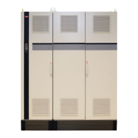
Illustration 3.5 Outside View
Crane System Design
VLT
®
Active Front End AFE 302 Operating Instructions Liebherr
12 MG.33.X2.02 - VLT
®
is a registered Danfoss trademark
3
3