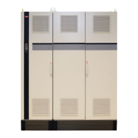
Illustration 3.11 One-drive Configuration
130BT255.10
9 9
11
11
12
13
18
19
27
29
32
33
20
33
64
Life Stop
55
12
13
18
19
27
29
32
33
20
33
64
Life Stop
55
Illustration 3.12 Two Independent Drive Configuration
M750-2267-GA
TRANSFORMEA
130BT256.10
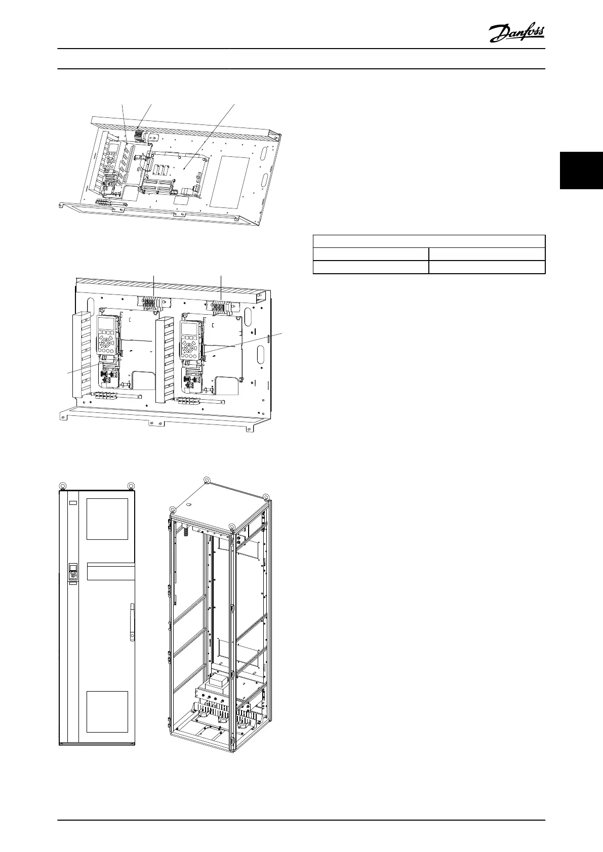
Illustration 3.13 Outside View and Cabinet Skeleton
3.2.4
MDCIC Connector Configuration
The MDCIC board has the four connectors. The ribbon cables
from the power units will be connected from FK100 to FK102
in this order. FK103 is reserved for the future use.
For one power unit configuration, the special part which
consists of the DC/DC converter and the ribbon cable is
connected to FK101. It generates an isolated 5V from an
internal 24V for the RS-485 port located at the control card.
MDCIC Port Layout
FK100 (Master) FK102 (Slave 2)
FK101 (Slave 1) FK103 (Empty
3.3 First Power Up/Commissioning Check
List
The following measurement equipment are recommended:
•
Voltage meter (1kA AC/DC env. Cat III)
•
Current clamp min. 2kA
•
Harmonic analyzer, only for commissioning
Check list
•
Check fan voltage supply (3x400V).
•
Verify that system is not powered.
•
Verify the system is grounded to earth.
1. all AFEs and frequency converters
2. all motors
3. all filters
4. the whole crane construction
5. HT transformer
•
Check that there are no earth faults or short circuits
at the motor cables and motors.
•
Check that the DC discharge resistor is connected
right and not shorted.
•
Verify phase sequence and continuity for the
voltage sensing on the AFE as described below.
1. Make sure that power is not applied.
2. Manually close input contactor (between
AFE and LCL filter).
3. Unplug the MK105 connector on the
MDCIC.
4. Measure MK105 of MDCIC harness to the
input phases.
Crane System Design
VLT
®
Active Front End AFE 302 Operating Instructions Liebherr
MG.33.X2.02 - VLT
®
is a registered Danfoss trademark 15
3
3