4 How to Install
This chapter covers mechanical and electrical installations to and from power terminals and control card terminals.
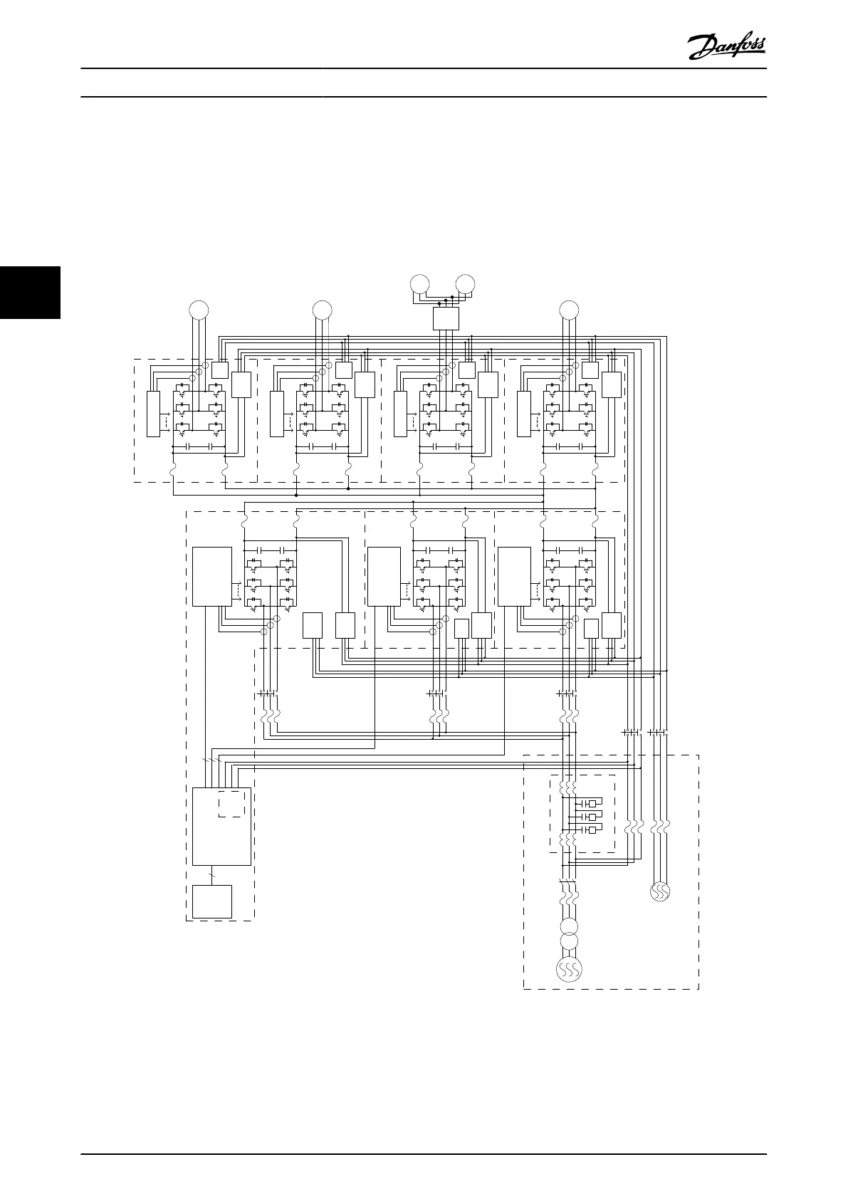
4.1 Overall Frequency Converter Configuration
Fuse
Fuse
Fuse
Fuse
Fuse
Fuse
Fuse
Fuse
Inv #1
Inv #2
Inv #3
Inv #4
R
S
T
LCL Filter
Fuse
Disconnect
Main PC
Sub PC1
Sub PC2
CT
CT
CT
gate signals
* Control gate signals
* Detect currents.
* Measure DC voltage.
* Control fans.
* Control gate signals
* Detect currents.
* Control fans.
* Control gate signals
* Detect currents.
* Control fans.
gate signals
gate signals
44
44
44
MDCIC
FC302
CC
44
MDCIC Functions:
* Distribute the gate signals.
* Combine the current signals and
send it as a total rec current.
Detect the overcurrent (IMAX1)
per module per phase.
* Detect the main voltage phase to
synchronize AFE (Only for AFE)
Voltage
Detection
Fan
Volt
Soft
Charge
Soft
Charge
AFE #3
Contactor
Fuse:
AFE #2
Contactor
AFE #1
Contactor
Soft
Charge
Soft
Charge
Soft
Charge
Soft
Charge
SC Wire Fuse
Fuse:
Fuse:
IM
Trolley
Travel
Fuse
Fuse
Fuse
Fuse
Fuse
Fuse
PC
PC
PC
PC
Soft
Charge
Fan
Volt
Fan
Volt
Fan
Volt
Fan
Volt
Fan
Volt
Fan
Volt
Fan Volt Wire Fuse
SC Contactor
Hoist Master
Abbreviations:
AFE: Active Front End
CC: Control Card
MDCIC: Multi-Drive Control
Interface Card
PC: Power Card
Fan Volt Supply
400V Contactor
400V
630V
Boom
Switch
IM
Hoist Master
IM
IM
IM
130BA683.10
Illustration 4.1 System Overview
How to Install
VLT
®
Active Front End AFE 302 Operating Instructions Liebherr
22 MG.33.X2.02 - VLT
®
is a registered Danfoss trademark
44