5.2 Parameters: 0-** Operation and Display
Parameters related to the basic functionality of the AFE.
Parameters related to the function of the display and
buttons.
5.2.1 0-0* Basic Settings
0-01 Language
Option: Function:
Defines the language to be used in the display.
[0] * English Part of Language packages 1 - 4
5.2.2 0-1* Set-up Operations
Define and control the individual parameter setups.
0-10 Active Set-up
Option: Function:
Select the set-up to control the frequency
converter functions.
[0] Factory
setup
Cannot be changed. It contains the Danfoss
data set, and can be used as a data source
when returning the other set-ups to a known
state.
[1] * Set-up 1
Set-up 1 [1] to Set-up 4 [4] are the four separate
parameter set-ups within which all parameters
can be programmed.
[2] Set-up 2
[3] Set-up 3
[4] Set-up 4
[9] Multi Set-up Remote selection of set-ups using digital
inputs and the serial communication port. This
set-up uses the settings from 0-12 This Set-up
Linked to. Stop the frequency converter before
making changes to open- and closed loop
functions
Required to use emergency mode.
0-11 Edit Set-up
Option: Function:
Editing can either follow the active setup
selection (par. 0-10), or be fixed at a setup
number. This parameter is unique for LCP and
buses.
[0] Factory setup
[1] * Set-up 1
[2] Set-up 2
[3] Set-up 3
[4] Set-up 4
[9] Active Set-up
0-12 This Set-up Linked to
Option: Function:
This parameter sets the AFE to automatically
synchronise the values of the 'not changeable
during operation' parameters between this set-
up and the set-up selected in this parameter.
Note: The values in this setup are overwritten.
[0] * Not linked
[1] Set-up 1
[2] Set-up 2
[3] Set-up 3
[4] Set-up 4
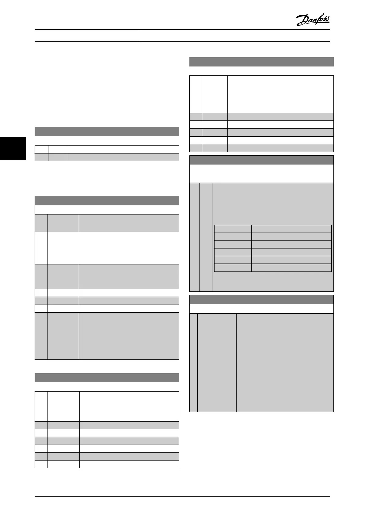
0-13 Readout: Linked Set-ups
Array [5]
Range: Function:
0
N/
A*
[0 -
255
N/
A]
View a list of all the set-ups linked by means of 0-12 This
Set-up Linked to. The parameter has one index for each
parameter set-up. The parameter value displayed for
each index represents which setups are linked to that
parameter setup.
Index LCP value
0 {0}
1 {1,2}
2 {1,2}
3 {3}
4 {4}
Table 5.2 Example: Set-up 1 and Set-up 2 are linked
0-14 Readout: Edit Set-ups / Channel
Range: Function:
0* [-2147483648 -
2147483647 ]
View the setting of 0-11 Edit Set-up for each
of the four different communication
channels. When the number is displayed in
hex, as it is in the LCP, each number
represents one channel.
Numbers 1-4 represent a set-up number; ‘F’
means factory setting; and ‘A’ means active
set-up. The channels are, from right to left:
LCP, FC-bus, USB, HPFB1-5.
Example: The number AAAAAA21h means
that the FC bus selected Set-up 2 in 0-11 Edit
Set-up, the LCP selected Set-up 1 and all
others used the active set-up.
How to Programme
VLT
®
Active Front End AFE 302 Operating Instructions Liebherr
34 MG.33.X2.02 - VLT
®
is a registered Danfoss trademark
55