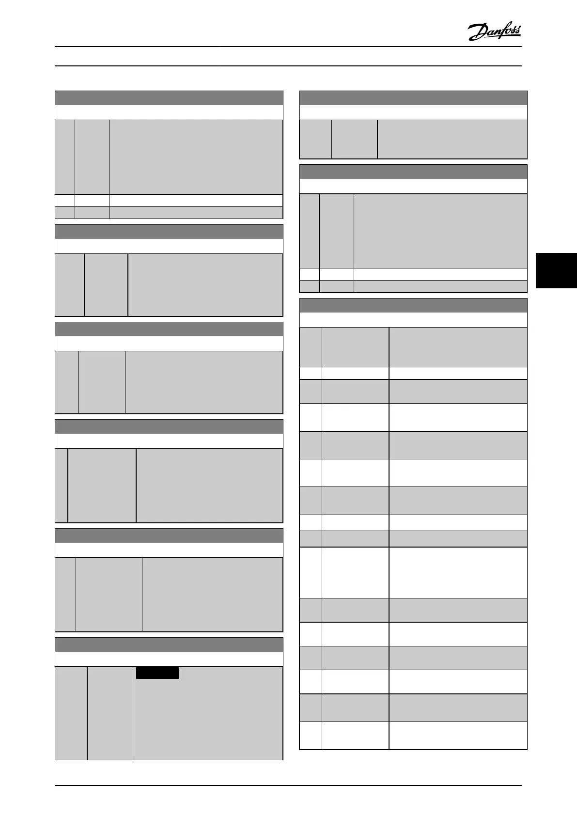
6-17 Terminal 53 Live Zero
Option: Function:
This parameter makes it possible to disable the
Live Zero monitoring. E.g. to be used if the
analog outputs are used as of a de-central I/O
system (e.g. when not as of any frequency
converter related control functions, but feeding a
Building Management system with data).
[0] Disabled
[1] * Enabled
6-20 Terminal 54 Low Voltage
Range: Function:
0.07 V* [ 0 - par.
6-21 V]
Enter the low voltage value. This analog
input scaling value should correspond to
the low reference/feedback value, set in
parameter 6-24 Terminal 54 Low Ref./Feedb.
Value.
6-21 Terminal 54 High Voltage
Range: Function:
10 V* [ par. 6-20
- 10 V]
Enter the high voltage value. This analog
input scaling value should correspond to the
high reference/feedback value set in
parameter 6-25 Terminal 54 High Ref./Feedb.
Value.
6-24 Terminal 54 Low Ref./Feedb. Value
Range: Function:
0* [-999999.999 -
999999.999 ]
Enter the analog input scaling value that
corresponds to the low voltage/low
current value set in
parameter 6-20 Terminal 54 Low Voltage
and parameter 6-22 Terminal 54 Low
Current.
6-25 Terminal 54 High Ref./Feedb. Value
Range: Function:
100* [-999999.999 -
999999.999 ]
Enter the analog input scaling value
that corresponds to the high voltage/
high current value set in
parameter 6-21 Terminal 54 High Voltage
and parameter 6-23 Terminal 54 High
Current.
6-26 Terminal 54 Filter Time Constant
Range: Function:
0.001 s* [0.001 -
10 s]
NOTICE
This parameter cannot be adjusted
while the motor is running.
Enter the time constant. This is a first-
order digital low pass filter time constant
for suppressing electrical noise in terminal
6-26 Terminal 54 Filter Time Constant
Range: Function:
54. A high time constant value improves
dampening but also increases the time
delay through the filter.
6-27 Terminal 54 Live Zero
Option: Function:
This parameter makes it possible to disable the
Live Zero monitoring. E.g. to be used if the
analog outputs are used as of a de-central I/O
system (e.g. when not as of any frequency
converter related control functions, but feeding a
Building Management System with data).
[0] Disabled
[1] * Enabled
6-50 Terminal 42 Output
Option: Function:
Select the function of Terminal 42 as
an analog current output. A motor
current of 20 mA corresponds to I
max
.
[0] No operation
[100] Output freq.
0-100
0-100 Hz, (0-20 mA)
[101] Reference Min-
Max
Minimum reference - Maximum
reference, (0-20 mA)
[102] Feedback +-200%
-200% to +200% of 20-14 Maximum
Reference/Feedb., (0-20 mA)
[103] Motor cur. 0-Imax
0 - Inverter Max. Current (16-37 Inv.
Max. Current), (0-20 mA)
[104] Torque 0-Tlim
0 - Torque limit (4-16 Torque Limit
Motor Mode), (0-20 mA)
[105] Torque 0-Tnom 0 - Motor rated torque, (0-20 mA)
[106] Power 0-Pnom 0 - Motor rated power, (0-20 mA)
[107] Speed 0-HighLim 0 - Speed High Limit
(parameter 4-13 Motor Speed High Limit
[RPM] and parameter 4-14 Motor Speed
High Limit [Hz]), (0-20 mA)
[113] Ext. Closed Loop
1
0-100%, (0-20 mA)
[114] Ext. Closed Loop
2
0-100%, (0-20 mA)
[115] Ext. Closed Loop
3
0-100%, (0-20 mA)
[130] Out frq 0-100
4-20mA
0-100 Hz
[131] Reference 4-20mA Minimum Reference - Maximum
Reference
[132] Feedback 4-20mA
-200% to +200% of 20-14 Maximum
Reference/Feedb.
How to Programme VLT HVAC Drive FC 102 Operating Instructions
MG11F402 - Rev. 2013-12-16 101
6 6
 Loading...


