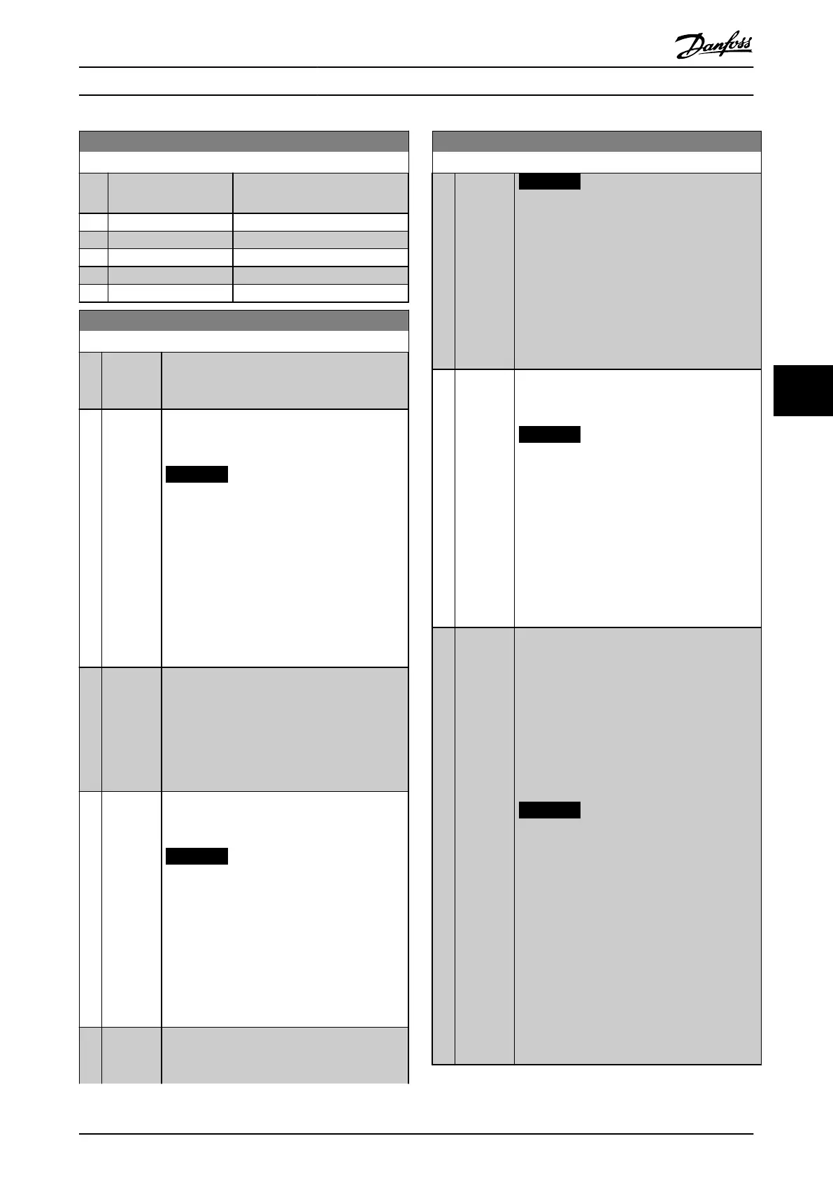
20-07 Feedback 3 Conversion
Option: Function:
See parameter 20-01 Feedback 1
Conversion for details.
[0] * Linear
[1] Square root
[2] Pressure to temperature
[3] Pressure to flow
[4] Velocity to flow
20-20 Feedback Function
Option: Function:
This parameter determines how the 3 possible
feedbacks are used to control the output
frequency of the frequency converter.
[0] Sum Sets up the PID Controller to use the sum of
Feedback 1, Feedback 2 and Feedback 3 as the
feedback.
NOTICE
Any unused feedbacks must be set to No
Function in parameter 20-00 Feedback 1
Source, parameter 20-03 Feedback 2
Source, or parameter 20-06 Feedback 3
Source.
The sum of Setpoint 1 and any other references
that are enabled (see parameter group 3-1*
References) are used as the PID Controller’s set-
point reference.
[1] Difference Sets up the PID controller to use the difference
between Feedback 1 and Feedback 2 as the
feedback. Feedback 3 is not used with this
selection. Only Setpoint 1 is used. The sum of
Setpoint 1 and any other references that are
enabled (see parameter group 3-1* References) are
used as the PID controller’s set-point reference.
[2] Average Sets up the PID Controller to use the average of
Feedback 1, Feedback 2 and Feedback 3 as the
feedback.
NOTICE
Any unused feedbacks must be set to No
Function in parameter 20-00 Feedback 1
Source, parameter 20-03 Feedback 2
Source, or parameter 20-06 Feedback 3
Source. The sum of Setpoint 1 and any
other references that are enabled (see
parameter group 3-1* References) are used
as the PID Controller’s set-point reference.
[3]
*
Minimum Sets up the PID Controller to com Feedback 1,
Feedback 2 and Feedback 3 and uses the lowest
value as the feedback.
20-20 Feedback Function
Option: Function:
NOTICE
Any unused feedbacks must be set to No
Function in parameter 20-00 Feedback 1
Source, parameter 20-03 Feedback 2
Source, or parameter 20-06 Feedback 3
Source. Only setpoint 1 is used. The sum
of Setpoint 1 and any other references
that are enabled (see parameter group
3-1* References) are used as the PID
Controller’s setpoint reference.
[4] Maximum Sets up the PID Controller to com Feedback 1,
Feedback 2 and Feedback 3 and use the highest
value as the feedback.
NOTICE
Any unused feedbacks must be set to No
Function in parameter 20-00 Feedback 1
Source, parameter 20-03 Feedback 2
Source, or parameter 20-06 Feedback 3
Source.
Only Setpoint 1 is used. The sum of Setpoint 1
and any other references that are enabled (see
parameter group 3-1* Referencdes) are used as
the PID Controller’s setpoint reference.
[5] Multi
Setpoint
Min
Sets up the PID Controller to calculate the
difference between Feedback 1 and Setpoint 1,
Feedback 2 and Setpoint 2, and Feedback 3 and
Setpoint 3. It uses the feedback/setpoint pair in
which the feedback is the farthest below its
corresponding setpoint reference. If all feedback
signals are above their corresponding setpoints,
the PID Controller uses the feedback/setpoint
pair in which the difference between the
feedback and setpoint is the least.
NOTICE
If only 2 feedback signals are used, the
feedback that is not to be used must be
set to [0] No Function in
parameter 20-00 Feedback 1 Source,
parameter 20-03 Feedback 2 Source or
parameter 20-06 Feedback 3 Source. Note
that each setpoint reference is the sum of
its respective parameter value
(parameter 20-21 Setpoint 1,
parameter 20-22 Setpoint 2 and
20-23 Setpoint 3) and any other references
that are enabled (see parameter group
3-1* References).
How to Programme VLT HVAC Drive FC 102 Operating Instructions
MG11F402 - Rev. 2013-12-16 105
6 6
 Loading...


