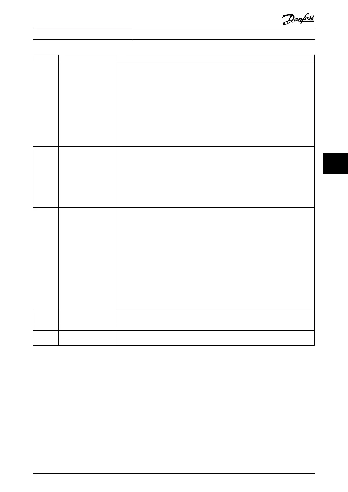
Group Title Function
4** Limits/Warnings Parameters used to program limits and warnings of operation including:
•
Allowable motor direction
•
Minimum and maximum motor speeds (e.g. in pump applications it is typical to program a
minimum speed to approx 30-40% to ensure pump seals are adequately lubricated at all
times, avoid cavitation and ensure adequate head is produced at all times to create flow)
•
Torque and current limits to protect the pump, fan or compressor driven by the motor
•
Warnings for low/high current, speed, reference, and feedback
•
Missing motor phase protection
•
Speed bypass frequencies including semi-automatic setup of these frequencies (e.g. to avoid
resonance conditions on cooling tower and other fans)
5** Digital In/Out Parameters used to program the functions of all
•
digital inputs
•
digital outputs
•
relay outputs
•
pulse inputs
•
pulse outputs
for terminals on the control card and all option cards.
6** Analog In/Out Parameters used to program the functions associated with all analog inputs and analog outputs
for the terminals on the control card and General Purpose I/O option (MCB 101) including:
•
Analog input live zero timeout function (which for example can be used to command a
cooling tower fan to operate at full speed if the condenser water return sensor fails)
•
Scaling of the analog input signals (for example to match the analog input to the mA and
pressure range of a static duct pressure sensor)
•
Filter time constant to filter out electrical noise on the analog signal which can sometimes
occur when long cables are installed
•
Function and scaling of the analog outputs (for example to provide an analog output
representing motor current or kW to an analog input of a DDC controller) and to configure
the analog outputs to be controlled by the BMS via a high level interface (HLI) (e.g. to
control a chilled water valve) including ability to define a default value of these outputs in
the event of the HLI failing
8** Communication and
Options
Parameters used for configuring and monitoring functions associated with the serial communi-
cations/high level interface to the frequency converter
9** Profibus Parameters only applicable when a Profibus option is installed.
10** CAN Fieldbus Parameters only applicable when a DeviceNet option is installed.
11** LonWorks Parameters only applicable when a Lonworks option is installed.
How to Programme VLT HVAC Drive FC 102 Operating Instructions
MG11F402 - Rev. 2013-12-16 81
6 6
 Loading...


