2.4 Electrical Installation
This section contains detailed instructions for wiring the
adjustable frequency drive. The following tasks are
described.
•
Wiring the motor to the adjustable frequency
drive output terminals
•
Wiring the AC line power to the adjustable
frequency drive input terminals
•
Connecting control and serial communication
wiring
•
After power has been applied, checking input
and motor power; programming control terminals
for their intended functions
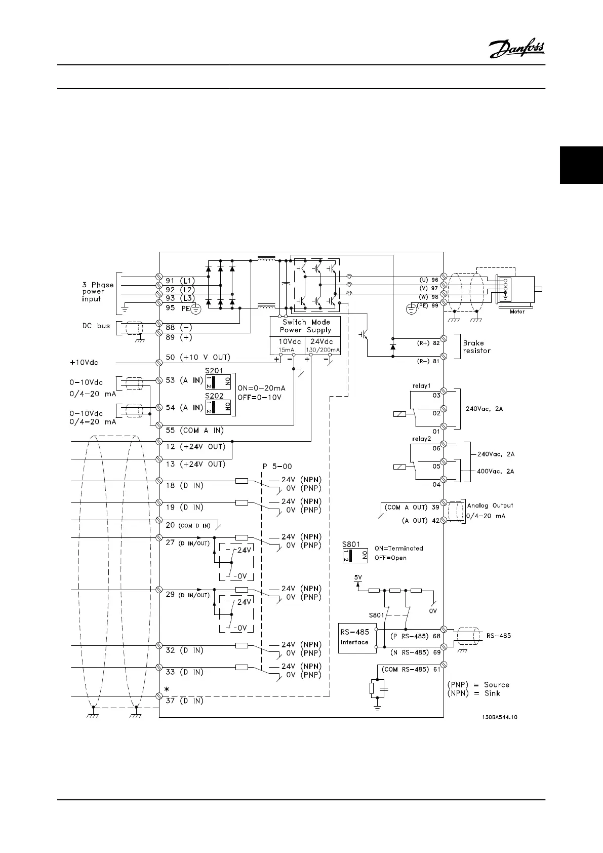
Figure 2.4 shows a basic electrical connection.
Figure 2.4 Basic Wiring Schematic Drawing.
* Terminal 37 is an option
Installation
VLT
®
AQUA Drive
Instruction Manual
MG20M922 - VLT
®
is a registered Danfoss trademark 2-3
2
2

 Loading...


