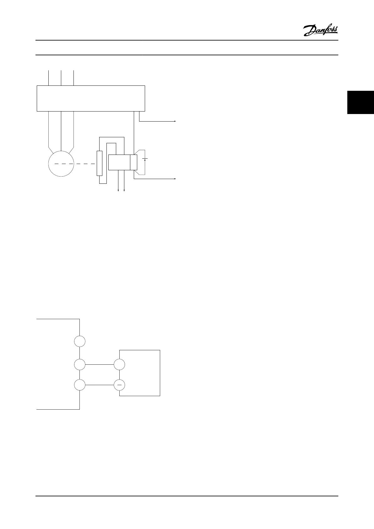
L1 L2 L3
U V W
02 01
A1
A2
130BA902.10
Drive
Output
relay
Command Circuit
220Vac
Mechanical
Brake
Shaft
Motor
Frewheeling
diode
Brake
380Vac
Output
Contactor
Input
Power Circuit
Figure 2.21 Connecting the Mechanical Brake to the
Adjustable Frequency Drive
2.4.6
Serial Communication
Connect RS-485 serial communication wiring to terminals
(+)68 and (-)69.
•
A shielded serial communication cable is
recommended
•
See 2.4.2 Grounding Requirements for proper
grounding
61
68
69
+
130BB489.10
RS-485
Figure 2.22 Serial Communication Wiring Diagram
For basic serial communication set-up, select the following
1.
Protocol type in 8-30 Protocol.
2. Adjustable frequency drive address in
8-31 Address.
3.
Baud rate in 8-32 Baud Rate.
•
Four communication protocols are internal to the
adjustable frequency drive. Follow the motor
manufacturer wiring requirements.
Danfoss FC
Modbus RTU
Johnson Controls N2
®
•
Functions can be programmed remotely using
the protocol software and RS-485 connection or
in parameter group 8-** Communications and
Options.
•
Selecting a specific communication protocol
changes various default parameter settings to
match that protocol’s specifications along with
making additional protocol-specific parameters
available
•
Option cards for the adjustable frequency drive
are available to provide additional communi-
cation protocols. See the option-card
documentation for installation and instruction
manual
Installation
VLT
®
AQUA Drive
Instruction Manual
MG20M922 - VLT
®
is a registered Danfoss trademark 2-13
2
2

 Loading...


