•
When factory installed optional equipment is
wired to terminal 27, do not remove that wiring.
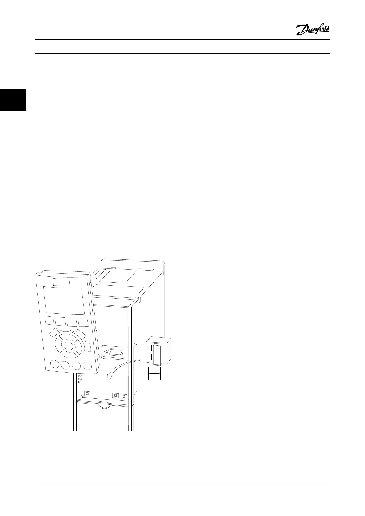
2.4.5.7 Terminal 53 and 54 Switches
•
Analog input terminals 53 and 54 can select
either voltage (0 to 10 V) or current (0/4–20 mA)
input signals
•
Remove power to the adjustable frequency drive
before changing switch positions.
•
Set switches A53 and A54 to select the signal
type. U selects voltage, I selects current.
•
The switches are accessible when the LCP has
been removed (see Figure 2.20). Note that some
option cards available for the unit may cover
these switches and must be removed to change
switch settings. Always remove power to the unit
before removing option cards.
•
Terminal 53 default is for a speed reference signal
in open-loop set in 16-61 Terminal 53 Switch
Setting
•
Terminal 54 default is for a feedback signal in
closed-loop set in 16-63 Terminal 54 Switch Setting
130BT310.10
1
2
N O
VLT
BUS TER.
OFF-ON
A53 A54
U- I U- I
Figure 2.20 Location of Terminals 53 and 54 Switches
2.4.5.8
Mechanical Brake Control
In hoisting/lowering applications, it is necessary to be able
to control an electro-mechanical brake:
•
Control the brake using any relay output or
digital output (terminal 27 or 29).
•
Keep the output closed (voltage-free) as long as
the adjustable frequency drive is unable to
‘support’ the motor, such as when the load is too
heavy, for example.
•
Select [32] Mechanical brake control in parameter
group 5-4* Relays for applications with an electro-
mechanical brake.
•
The brake is released when the motor current
exceeds the preset value in 2-20 Release Brake
Current.
•
The brake is engaged when the output frequency
is less than the frequency set in 2-21 Activate
Brake Speed [RPM] or 2-22 Activate Brake Speed
[Hz], and only if the adjustable frequency drive
carries out a stop command.
If the adjustable frequency drive is in alarm mode or in an
overvoltage situation, the mechanical brake immediately
cuts in.
In the vertical movement, the key point is that the load
must be held, stopped, controlled (raised, lowered) in a
safe mode during the entire operation. Because the
adjustable frequency drive is not a safety device, the
crane/lift designer (OEM) must decide on the type and
number of safety devices (e.g., speed switch, emergency
brakes, etc.) to be used, in order to be able to stop the
load in case of emergency or malfunction of the system,
according to relevant national crane/lift regulations.
Installation
VLT
®
AQUA Drive
Instruction Manual
2-12 MG20M922 - VLT
®
is a registered Danfoss trademark
2
2

 Loading...


