•
Ground the cable in accordance with grounding
instructions provided.
•
Torque terminals in accordance with the
information provided in 10.4.1 Connection
Tightening Torques
•
Follow the motor manufacturer wiring
requirements
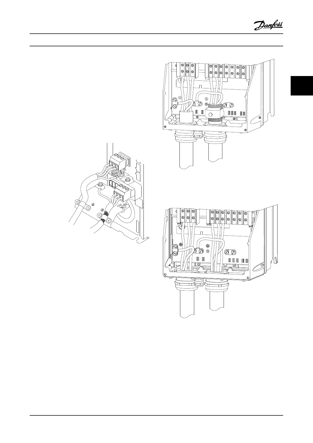
The three following figures represent line power input,
motor, and ground for basic adjustable frequency drives.
Actual configurations vary with unit types and optional
equipment.
130BA266.10
+DC
BR-
B
MAINS
L1 L2 L3
91 92 93
RELAY 1 RELAY 2
99
- LC -
UVW
MOTOR
Figure 2.8 Motor, Line Power and Ground
Wiring for A-Frame Sizes
91
L1
92
L2
93
L3
96
U
97
V
98
W
88
DC-
89
DC+
81
R-
8
R+
130BA390.11
99
95
Figure 2.9 Motor, Line Power and Ground Wiring
for B-Frame Sizes and Above Using
Shielded Cable
130BB477.10
91
L1
92
L2
93
L3
96
U
97
V
99
W
88
DC+
89
DC-
91
R-
9
R+
95
99
Figure 2.10 Motor, Line Power and Ground Wiring
for B-Frame Sizes and Above Using Conduit
Installation
VLT
®
AQUA Drive
Instruction Manual
MG20M922 - VLT
®
is a registered Danfoss trademark 2-7
2
2

 Loading...


