Cable lengths and cross-sections
Max. motor cable length, shielded/armored 500 ft [150 m]
Max. motor cable length, unshielded/unarmored 1000 ft [300 m]
Max. cross-section to motor, line power, load sharing and brake *
Maximum cross-section to control terminals, rigid wire 1.5 mm
2
/16 AWG (2 x 0.75 mm
2
)
Maximum cross-section to control terminals, flexible cable 0.0016 in
2
[1 mm
2
]/18 AWG
Maximum cross-section to control terminals, cable with enclosed core 0.5 mm
2
/20 AWG
Minimum cross-section to control terminals 0.00039 in
2
[0.25 mm
2
]
* See Line Power Supply tables for more information!
Control card, RS-485 serial communication
Terminal number 68 (P,TX+, RX+), 69 (N,TX-, RX-)
Terminal number 61 Common for terminals 68 and 69
The RS-485 serial communication circuit is functionally seated from other central circuits and galvanically isolated from the
supply voltage (PELV).
Analog inputs
Number of analog inputs 2
Terminal number 53, 54
Modes Voltage or current
Mode select Switch S201 and switch S202
Voltage mode Switch S201/switch S202 = OFF (U)
Voltage level 0 to +10 V (scaleable)
Input resistance, R
i
approx. 10 kΩ
Max. voltage ±20 V
Current mode Switch S201/switch S202 = ON (I)
Current level 0/4 to 20 mA (scaleable)
Input resistance, R
i
approx. 200 Ω
Max. current 30 mA
Resolution for analog inputs 10 bit (+ sign)
Accuracy of analog inputs Max. error 0.5% of full scale
Bandwidth 200 Hz
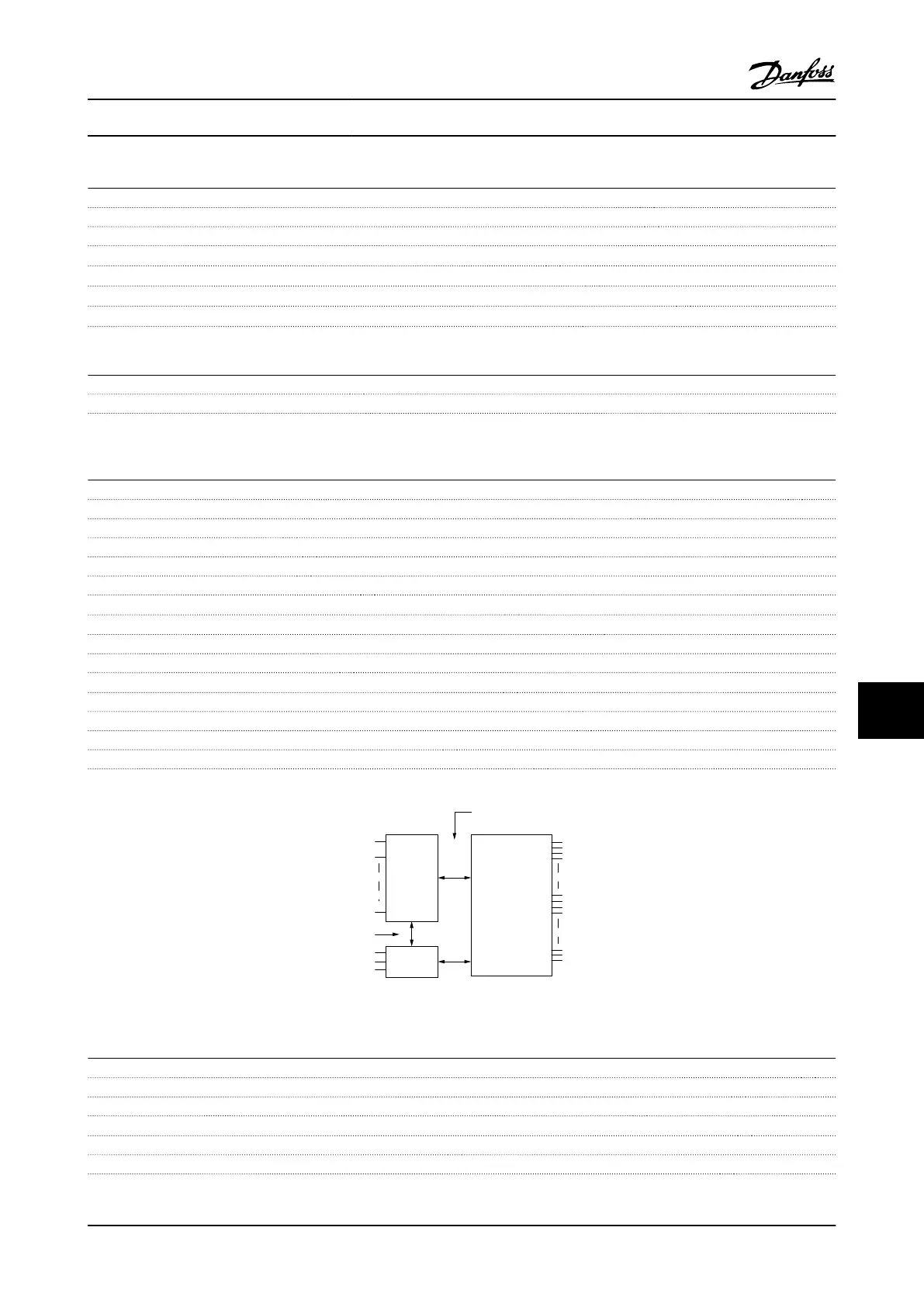
The analog inputs are galvanically isolated from the supply voltage (PELV) and other high-voltage terminals.
Mains
Functional
isolation
PELV isolation
Motor
DC-Bus
High
voltage
Control
+24V
RS485
18
37
130BA117.10
Figure 10.1 PELV Isolation of Analog Inputs
Analog output
Number of programmable analog outputs 1
Terminal number 42
Current range at analog output 0/4–20 mA
Max. resistor load to common at analog output 500 Ω
Accuracy on analog output Max. error: 0.8% of full scale
Resolution on analog output 8 bit
The analog output is galvanically isolated from the supply voltage (PELV) and other high-voltage terminals.
Specifications
VLT
®
AQUA Drive
Instruction Manual
MG20M922 - VLT
®
is a registered Danfoss trademark 10-13
10
10

 Loading...


