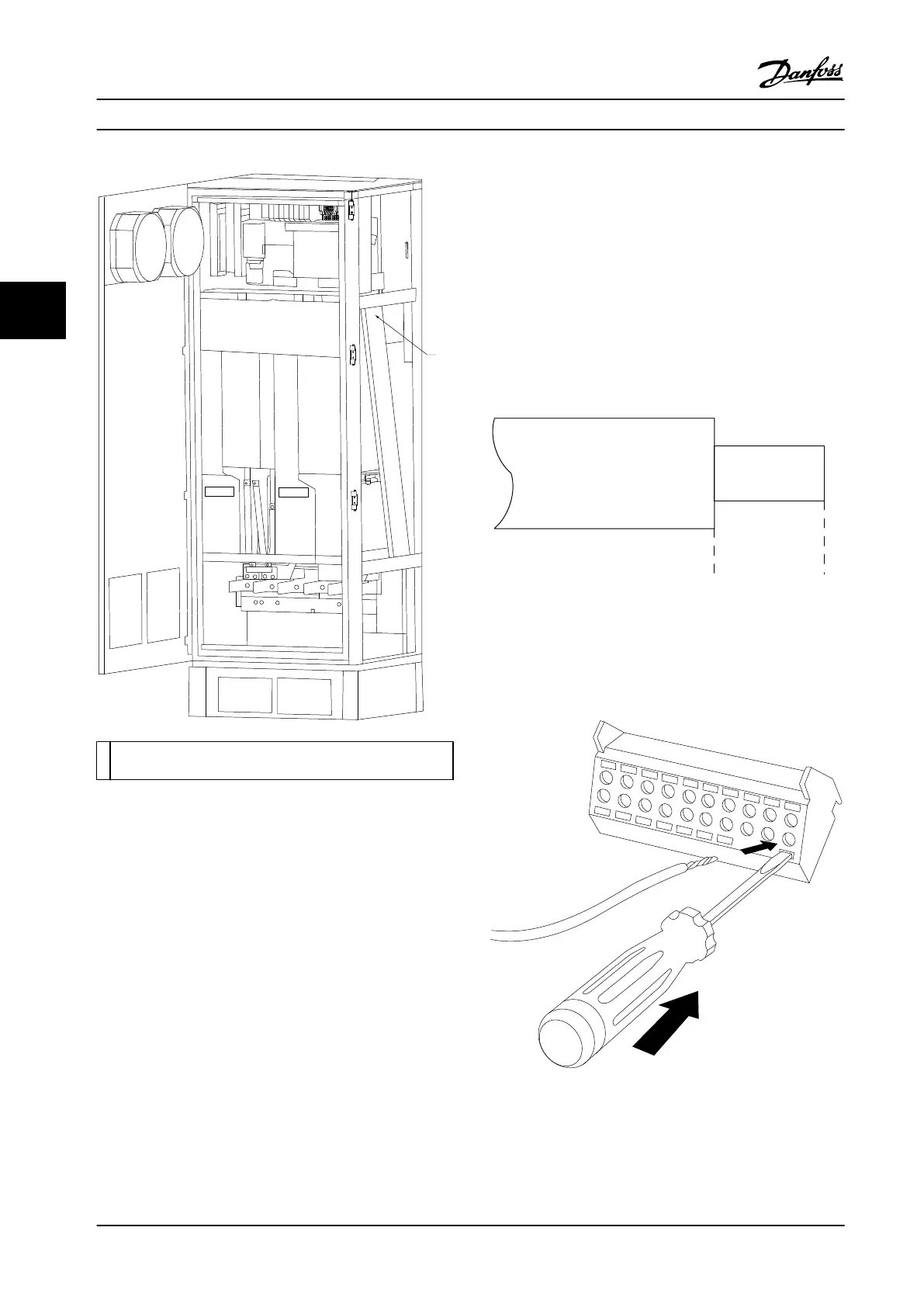
1 Routing path for the control card wiring, inside the adjustable
frequency drive enclosure.
Figure 4.7 Control Card Wiring Path for Frame Size F18
4.8.2 Access to Control Terminals
All terminals to the control cables are located beneath the
LCP (both lter and adjustable frequency drive LCP). They
are accessed by opening the door of the unit.
4.8.3 Electrical Installation, Control
Terminals
To connect the cable to the terminal:
1. Strip insulation by about 0.35–0.4 in [9–10 mm]
Electrical installationControl terminals
130BA150.10
9 - 10 mm
(0.37 in)
Figure 4.8 Length to Strip the Insulation
2. Insert a screwdriver (max. 0.016x0.1 in [0.4x2.5
mm]) in the square hole.
3. Insert the cable in the adjacent circular hole.
Figure 4.9 Inserting the Cable in the Terminal Block
4. Remove the screwdriver. The cable is now
mounted in the terminal.
Electrical Installation
VLT
®
AQUA Drive FC 202 Low Harmonic Drive
42 Danfoss A/S © 10/2015 All rights reserved. MG21B322
44

 Loading...


