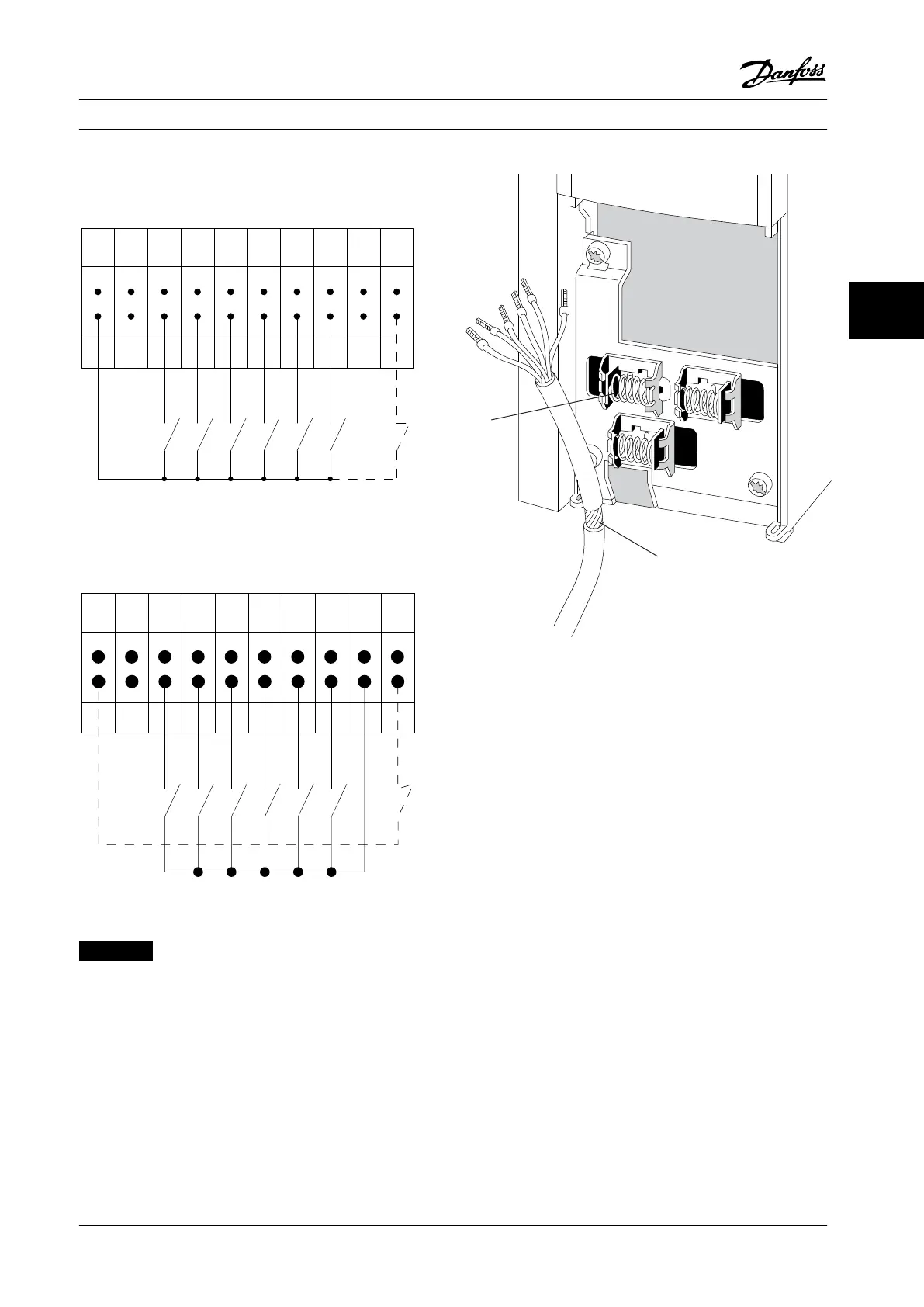
12 13 18 19 27 29 32 33 20 37
+24 V DC
0 VDC
130BT106.10
PNP (Source)
Digital input wiring
Figure 4.13 Input Polarity of Control Terminals, PNP
NPN (Sink)
Digital input wiring
12 13 18 19 27 29 32 33 20 37
+24 V DC
0 VDC
130BT107.11
Figure 4.14 Input Polarity of Control Terminals, NPN
NOTICE!
To comply with EMC emission specications, shielded/
armored cables are recommended. If using non-shielded/
armored cable, see chapter 4.7.3 Power and Control Wiring
for Non-shielded Cables. If using non-shielded control
cables, use ferrite cores to improve EMC performance.
Figure 4.15 Connecting Shielded Cables
Connect the shields in a proper way to ensure optimum
electrical immunity.
4.8.5 Safe Torque O (STO)
To run STO, additional wiring for the frequency converter is
required. Refer to VLT
®
Frequency Converters Safe Torque O
Operating Instructions for further information.
Electrical Installation Installation Manual
MG21B322 Danfoss A/S © 10/2015 All rights reserved. 45
4 4

 Loading...


