4.8.4 Electrical Installation, Control Cables
130BD429.10
DC bus
Switch Mode
Power Supply
Motor
Analog Output
Interface
relay1
relay2
(PNP) = Source
(NPN) = Sink
ON=Terminated
OFF=Open
Brake
resistor
PE
88 (-)
89 (+)
50 (+10 V OUT)
53 (A IN)
54 (A IN)
55 (COM A IN)
0/4-20 mA
12 (+24V OUT)
13 (+24V OUT)
37 (D IN)
18 (D IN)
20 (COM D IN)
10Vdc
15mA 130/200mA
+ - + -
(U) 96
(V) 97
(W) 98
(PE) 99
(COM A OUT) 39
(A OUT) 42
(P RS-485) 68
(N RS-485) 69
(COM RS-485) 61
0V
5V
S801
0/4-20 mA
RS-485
RS-485
03
+10Vdc
-10Vdc -
+10Vdc
+10Vdc
0/4-20 mA
-10Vdc -
240Vac, 2A
24Vdc
02
01
05
04
06
240Vac, 2A
24V (NPN)
0V (PNP)
0V (PNP)
24V (NPN)
19 (D IN)
24V (NPN)
0V (PNP)
27
24V
0V
(D IN/OUT)
0V (PNP)
24V (NPN)
(D IN/OUT)
0V
24V
29
24V (NPN)
0V (PNP)
0V (PNP)
24V (NPN)
33 (D IN)
32 (D IN)
1 2
ON
S201
ON
21
S202
ON/I=0-20mA
OFF/U=0-10V
95
400Vac, 2A
P 5-00
21
ON
S801
(R+) 82
(R-) 81
*
*
Optional
RFI
Optional
Fuses
Optional
Manual
Disconnect
HI Reactor
L
m
L
m
L
m
L
ac
L
ac
L
ac
AC
Contactor
Relay 12
Control & AUX
Feedback
Relay 12
Control & AUX
Feedback
Soft-Charge
Converter
Side Filter
Power Stage
AF Current
Sensors
Capacitor
Current Sensors
3
3
NC
Relay
L
c
L
c
L
c
C
ef
C
ef
C
ef
R
ef
R
ef
R
ef
I
r
I
s
I
t
91 (L1)
92 (L2)
93 (L3)
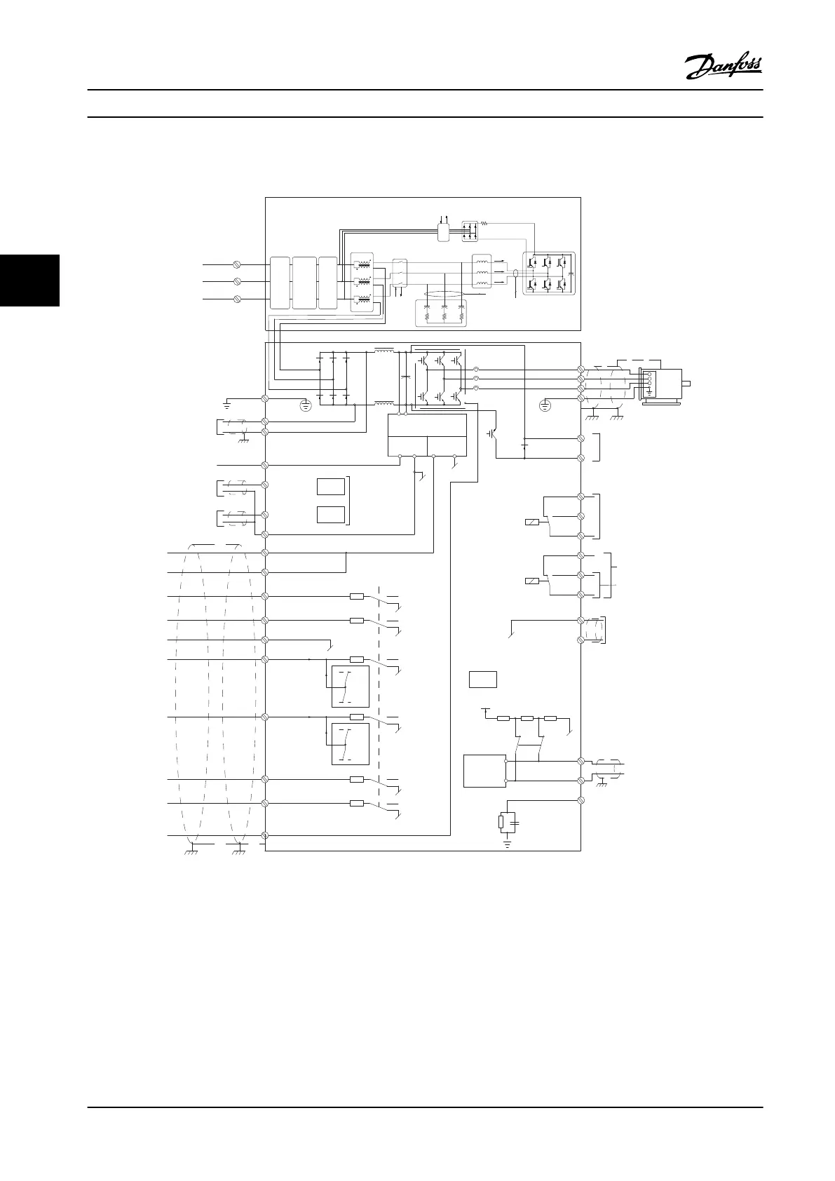
Figure 4.12 Terminal Diagram
Long control cables and analog signals may result in 50/60
Hz ground loops due to noise from line power supply
cables.
If ground loops occur, break the shield or insert a 100 nF
capacitor between shield and chassis, if needed.
Connect the digital and analog inputs and outputs to the
control cards of the units separately to avoid ground
currents. These connections are on terminals 20, 55, and 39
for both the lter and adjustable frequency drive sections.
Electrical Installation
VLT
®
AQUA Drive FC 202 Low Harmonic Drive
44 Danfoss A/S © 10/2015 All rights reserved. MG21B322
44

 Loading...


