EasyManuals Logo

Danfoss vlt aqua Design Guide

Danfoss vlt aqua
228 pages
To Next Page IconTo Next Page
To Previous Page IconTo Previous Page
Page #120 background imageLoading...
Page #120 background image
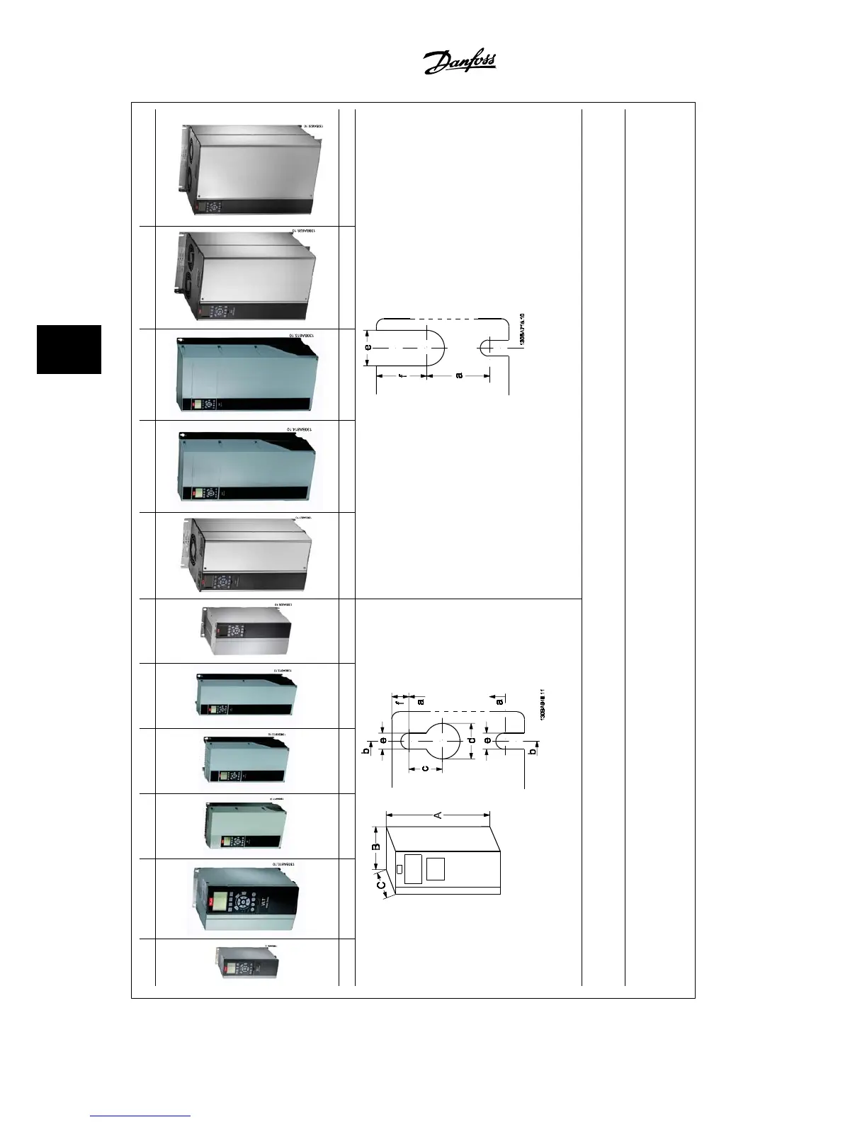
A2 A3 A5 B1 B2 B3 B4 C1 C2 C3 C4
IP20/21 IP20/21 IP55/66 IP21/55/66 IP21/55/66 IP20 IP20 IP21/55/66 IP21/55/66 IP20 IP20
Figure 5.1: Top and bottom mounting holes.
Figure 5.2: Top and bottom mounting holes. (B4+C3+C4 only)
Accessory bags containing necessary brackets, screws and connectors are included with the drives upon delivery.
All measurements in mm.
5.1.1 Mechanical Front Views
5 How to Install VLT
®
AQUA Drive Design Guide
5-2
MG.20.N5.22 - VLT
®
is a registered Danfoss trademark
5

Table of Contents

Other manuals for Danfoss vlt aqua

Questions and Answers:

Question and Answer IconNeed help?

Do you have a question about the Danfoss vlt aqua and is the answer not in the manual?

Danfoss vlt aqua Specifications

General IconGeneral
Supply Voltage200-240V, 380-500V, 525-600V
EnclosureIP20
FeaturesEnergy optimization
ApprovalsCE, UL, cUL
Input Voltage Range200-240V, 380-500V, 525-600V
Output Voltage Range0 to supply voltage
Protection FeaturesOvervoltage, Undervoltage, Overcurrent, Short circuit, Ground fault
Communication InterfacesPROFIBUS
Cooling MethodAir-cooled

Related product manuals