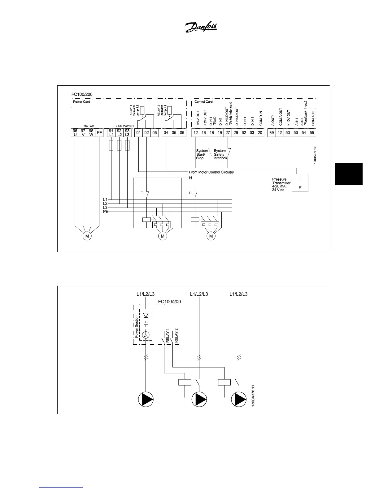
6.1.10 Cascade Controller Wiring Diagram
The wiring diagram shows an example with the built-in BASIC cascade controller with one variable speed pump (lead) and two fixed speed pumps, a 4–
20 mA transmitter and system safety interlock.
6.1.11 Fixed Variable Speed Pump Wiring Diagram
VLT
®
AQUA Drive Design Guide 6 Application Examples
MG.20.N5.22 - VLT
®
is a registered Danfoss trademark
6-7
6

 Loading...


