2.8 Control Structures
2.8.1 Control Principle
Figure 2.3: Control structures.
The adjustable frequency drive is a high performance unit for demanding applications. It can handle various kinds of motor control principles such as U/
f special motor mode and VVC plus and can handle normal squirrel cage asynchronous motors.
Short circuit behavior on this adjustable frequency drive depends on the 3 current transducers in the motor phases.
In
par. 1-00 Configuration Mode,
it is possible to select whether either
open-loop or closed-loop is to be used
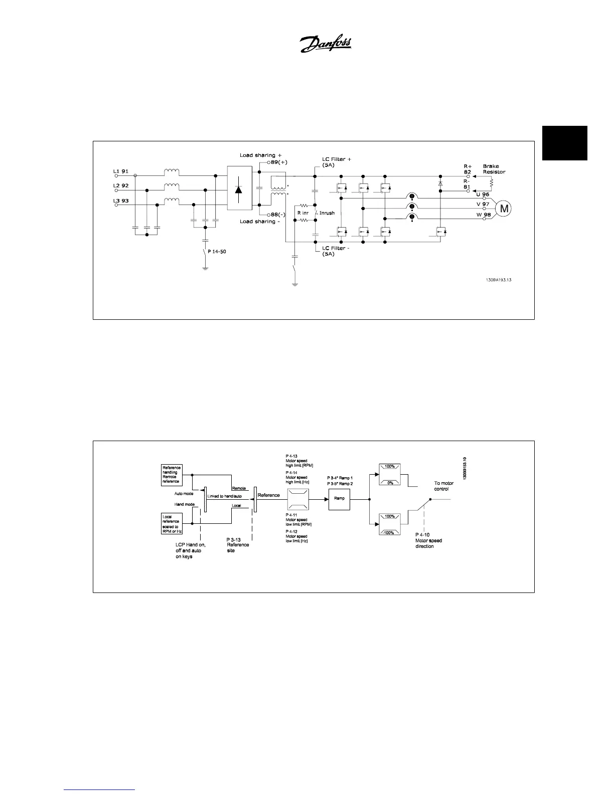
2.8.2 Control Structure Open-loop
Figure 2.4: Open-loop structure.
In the configuration shown in the illustration above,
par. 1-00 Configuration Mode
is set to Open-loop [0]. The resulting reference from the reference
handling system or the local reference is received and fed through the ramp limitation and speed limitation before being sent to the motor control.
The output from the motor control is then limited by the maximum frequency limit.
VLT
®
AQUA Drive Design Guide 2 Introduction to the VLT AQUA Drive
MG.20.N5.22 - VLT
®
is a registered Danfoss trademark
2-11
2
 Loading...


