EasyManuals Logo

Danfoss vlt aqua Design Guide

Danfoss vlt aqua
228 pages
To Next Page IconTo Next Page
To Previous Page IconTo Previous Page
Page #79 background imageLoading...
Page #79 background image
Warning Dual supply
How to add the MCB 105 option:
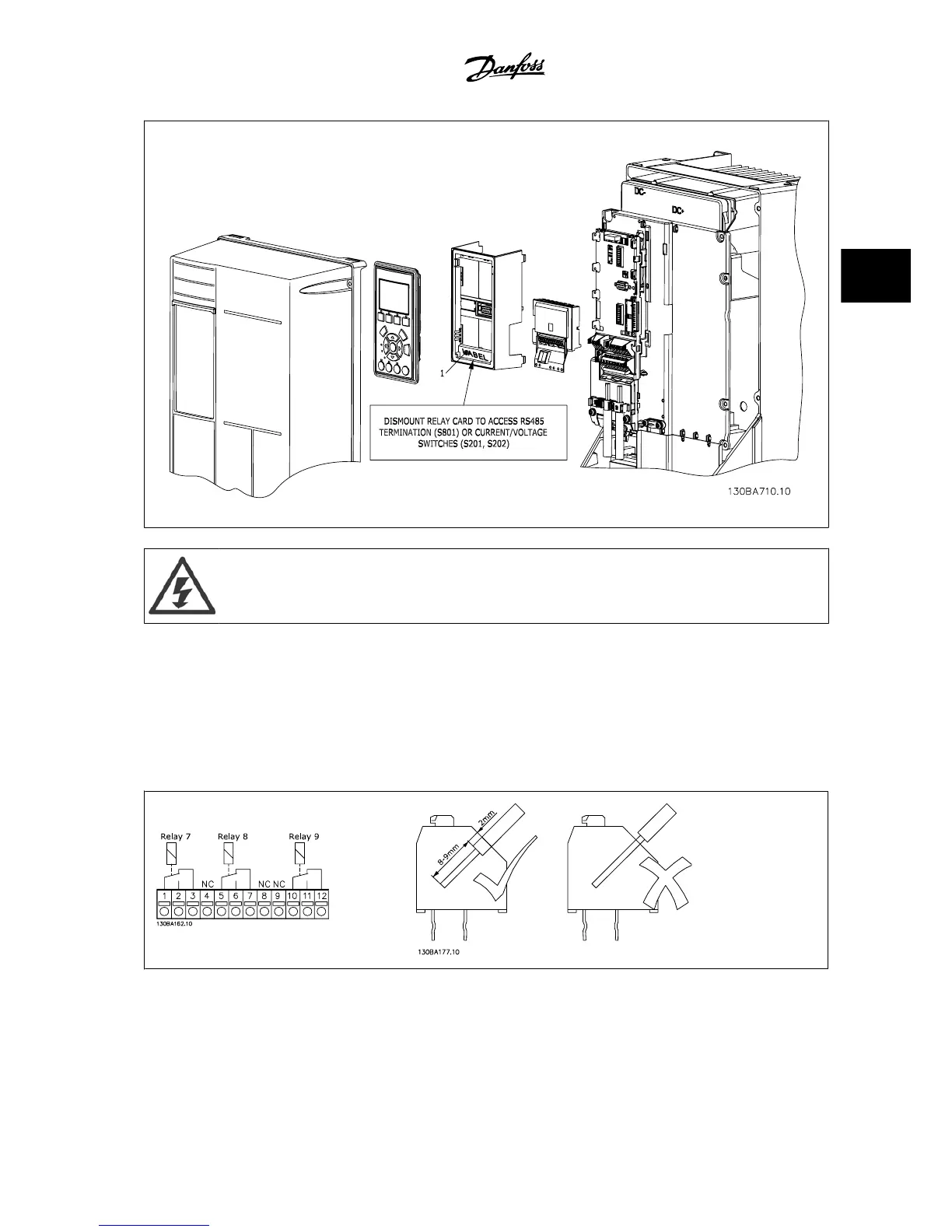
See the mounting instructions at the beginning of the section Options and Accessories.
The power to the live part connections on relay terminals must be disconnected.
Do not mix live parts (high voltage) with control signals (PELV).
Select the relay functions in par. 5-40
Function Relay
[6-8], par. 5-41
On Delay, Relay
[6-8] and par. 5-42
Off Delay, Relay
[6-8].
NB! (Index [6] is relay 7, index [7] is relay 8, and index [8] is relay 9)
VLT
®
AQUA Drive Design Guide 3 VLT AQUA Selection
MG.20.N5.22 - VLT
®
is a registered Danfoss trademark
3-35
3

Table of Contents

Other manuals for Danfoss vlt aqua

Questions and Answers:

Question and Answer IconNeed help?

Do you have a question about the Danfoss vlt aqua and is the answer not in the manual?

Danfoss vlt aqua Specifications

General IconGeneral
Supply Voltage200-240V, 380-500V, 525-600V
EnclosureIP20
FeaturesEnergy optimization
ApprovalsCE, UL, cUL
Input Voltage Range200-240V, 380-500V, 525-600V
Output Voltage Range0 to supply voltage
Protection FeaturesOvervoltage, Undervoltage, Overcurrent, Short circuit, Ground fault
Communication InterfacesPROFIBUS
Cooling MethodAir-cooled

Related product manuals