EasyManuals Logo

Danfoss vlt aqua Design Guide

Danfoss vlt aqua
228 pages
To Next Page IconTo Next Page
To Previous Page IconTo Previous Page
Page #126 background imageLoading...
Page #126 background image
Figure 5.3: Mounting Template
5.2.4 Lifting
Always lift the adjustable frequency drive using the dedicated lifting holes. For all D and E2 (IP00) frames, use a bar to avoid bending the lifting holes of
the adjustable frequency drive.
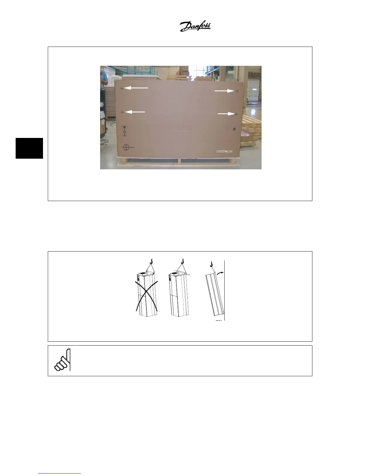
Figure 5.4: Recommended lifting method, frame sizes D and E .
NOTE!
The lifting bar must be able to handle the weight of the adjustable frequency drive. See
Mechanical Dimensions
for the weight of the
different frame sizes. Maximum diameter for bar is 1 in [25 cm]. The angle from the top of the drive to the lifting cable should be 60
degrees or greater.
5 How to Install VLT
®
AQUA Drive Design Guide
5-8
MG.20.N5.22 - VLT
®
is a registered Danfoss trademark
5

Table of Contents

Other manuals for Danfoss vlt aqua

Questions and Answers:

Question and Answer IconNeed help?

Do you have a question about the Danfoss vlt aqua and is the answer not in the manual?

Danfoss vlt aqua Specifications

General IconGeneral
Supply Voltage200-240V, 380-500V, 525-600V
EnclosureIP20
FeaturesEnergy optimization
ApprovalsCE, UL, cUL
Input Voltage Range200-240V, 380-500V, 525-600V
Output Voltage Range0 to supply voltage
Protection FeaturesOvervoltage, Undervoltage, Overcurrent, Short circuit, Ground fault
Communication InterfacesPROFIBUS
Cooling MethodAir-cooled

Related product manuals