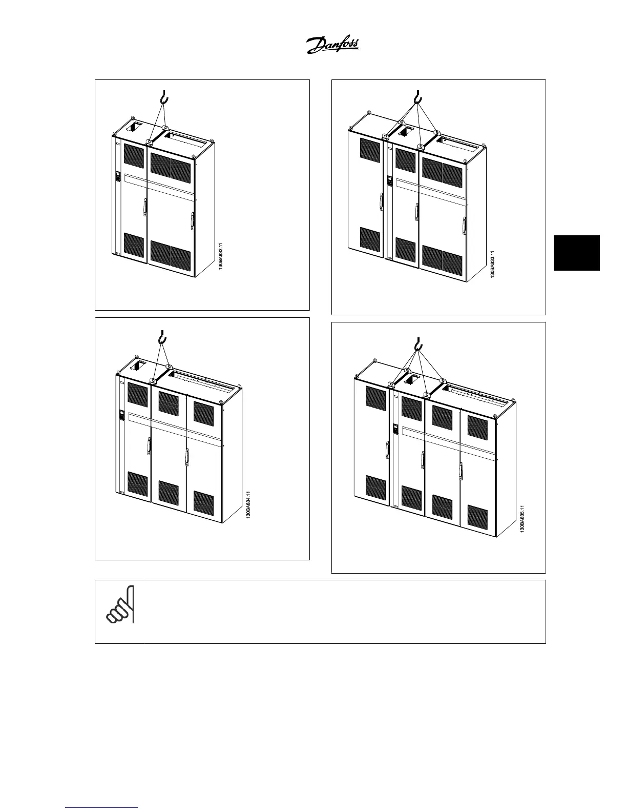
Figure 5.5: Recommended lifting method, frame size F1.
Figure 5.6: Recommended lifting method, frame size F2.
Figure 5.7: Recommended lifting method, frame size F3.
Figure 5.8: Recommended lifting method, frame size F4.
NOTE!
Note the plinth is provided in the same packaging as the adjustable frequency drive but is not attached to Unit SizesF1-F461-64 frames
during shipment. The plinth is required to allow airflow to the drive to provide proper cooling. The Unit SizesF6 frames should be
positioned on top of the plinth in the final installation location. The angle from the top of the drive to the lifting cable should be 60
degrees or greater.
VLT
®
AQUA Drive Design Guide 5 How to Install
MG.20.N5.22 - VLT
®
is a registered Danfoss trademark
5-9
5

 Loading...


