5.2.5 Tools Needed
To perform the mechanical installation, the following tools are needed:
• Drill with 0.39 or 0.47 in [10 or 12 mm] drill.
• Tape measure
• Wrench with relevant metric sockets (0.28-0.67 in (7-17 mm))
• Extensions to wrench
• Sheet metal punch for conduits or cable connectors in IP 21/Nema 1 and IP 54 units
• Lifting bar to lift the unit (rod or tube max. Ø1 in [25 mm], able to lift minimum 880 lbs [400 kg].
• Crane or other lifting aid to place the adjustable frequency drive in position
• A Torx T50 tool is needed to install the E1 in IP21 and IP54 enclosure types.
5.2.6 General Considerations
Space
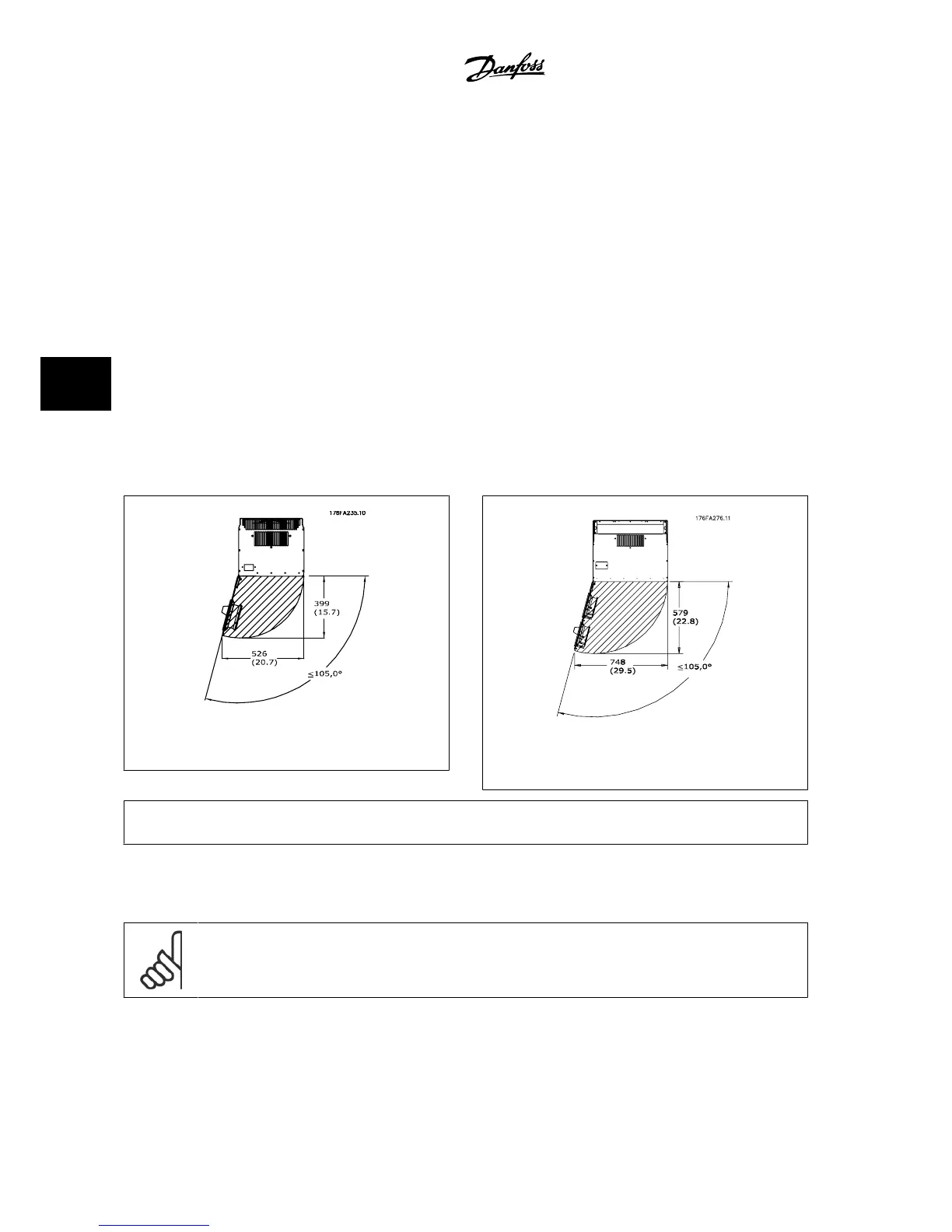
Ensure proper space above and below the adjustable frequency drive to allow airflow and cable access. In addition, space in front of the unit must be
considered to allow the panel door to be opened.
Figure 5.9: Space in front of IP21/IP54 enclosure type,
frame size D1 and D2.
Figure 5.10: Space in front of IP21/IP54 enclosure type,
frame size E1.
NOTE!
For frame size F, please see section
Mechanical Installation High Power
.
Wire access
Ensure that proper cable access is present including the necessary bending allowance. As the IP00 enclosure is open to the bottom cables must be fixed
to the back panel of the enclosure where the adjustable frequency drive is mounted, i.e., by using cable clamps.
NOTE!
All cable lugs/shoes must mount within the width of the terminal bus bar.
5 How to Install VLT
®
AQUA Drive Design Guide
5-10
MG.20.N5.22 - VLT
®
is a registered Danfoss trademark
5

 Loading...


