3.6 Options and Accessories
Danfoss offers a wide range of options and accessories for adjustable frequency drives.
3.6.1 Mounting Option Modules in Slot B
The power to the adjustable frequency drive must be disconnected.
For A2 and A3 enclosures:
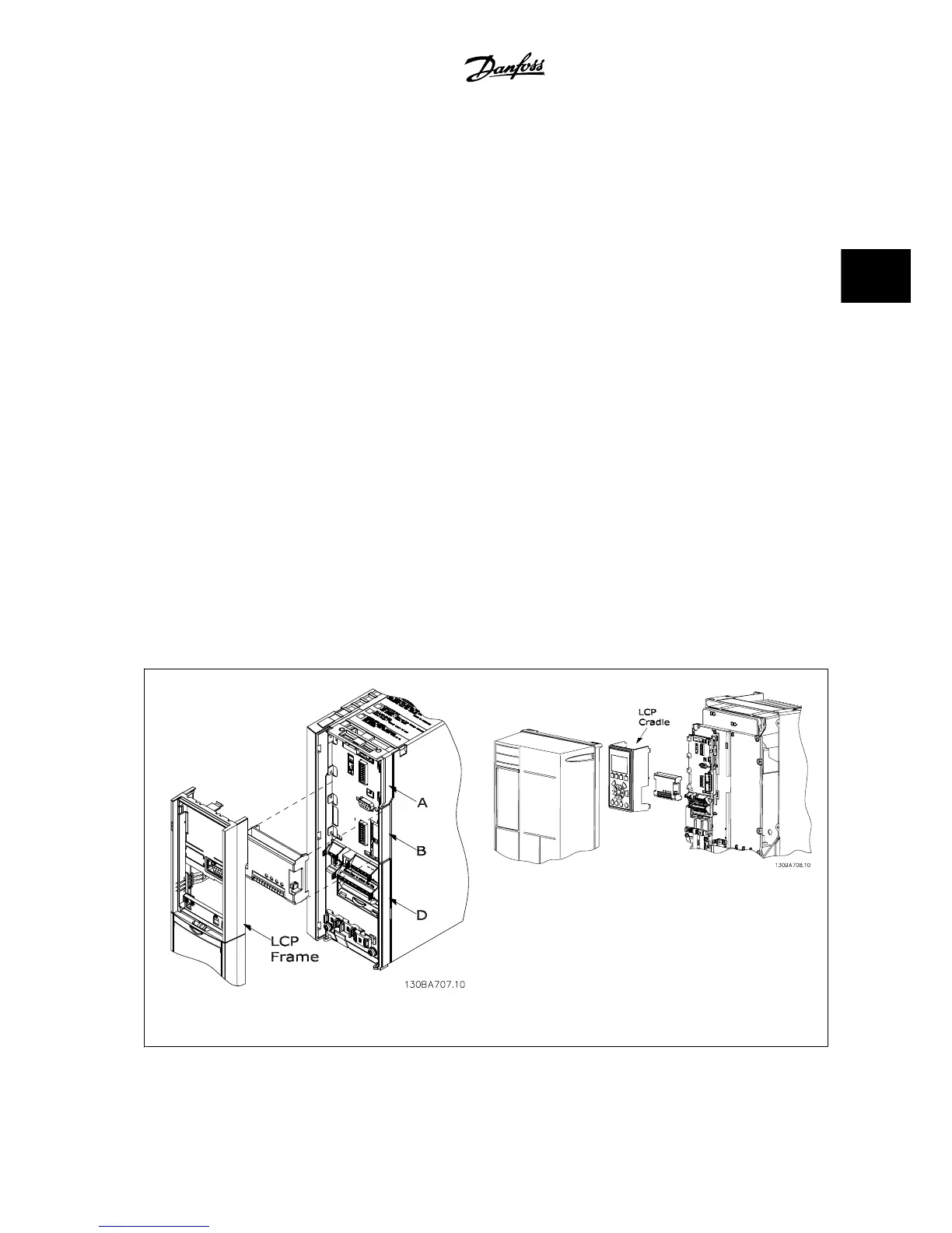
• Remove the LCP (Local Control Panel), the terminal cover, and the LCP frame from the adjustable frequency drive.
• Insert the MCB10x option card into slot B.
• Connect the control cables and fasten the cables with the enclosed cable strips.
Remove the knock-out in the extended LCP frame delivered in the option set so that the option will fit under the extended LCP frame.
• Fit the extended LCP frame and terminal cover.
• Fit the LCP or blind cover in the extended LCP frame.
• Connect power to the adjustable frequency drive.
• Set up the input/output functions in the corresponding parameters, as mentioned in the section
General Technical Data
.
For B1, B2, C1 and C2 enclosures:
• Remove the LCP and the LCP cradle
• Fit the MCB 10x option card into slot B.
• Connect the control cables and relieve the cable by the enclosed cable strips.
• Fit the cradle.
•Fit the LCP
A2, A3 and B3 enclosures A5, B1, B2, B4, C1, C2, C3 and C4 enclosures
VLT
®
AQUA Drive Design Guide 3 VLT AQUA Selection
MG.20.N5.22 - VLT
®
is a registered Danfoss trademark
3-31
3
 Loading...


