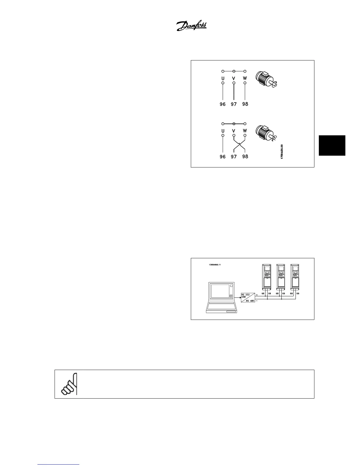
5.8.3 Direction of Motor Rotation
The default setting is clockwise rotation with the adjustable frequency
drive output connected as follows.
Terminal 96 connected to U-phase
Terminal 97 connected to V-phase
Terminal 98 connected to W-phase
The direction of motor rotation is changed by switching two motor pha-
ses.
Motor rotation check can be performed using par. 1-28
Motor Rotation
Check
and following the steps shown in the display.
5.8.4 Motor Thermal Protection
The electronic thermal relay in the adjustable frequency drive has received the UL approval for single motor protection, when par. 1-90
Motor Thermal
Protection
is set for
ETR Trip
and par. 1-24
Motor Current
is set to the rated motor current (see motor nameplate).
5.9 Installation of misc. connections
5.9.1 RS-485 Bus Connection
One or more adjustable frequency drives can be connected to a control
(or master) using the RS-485 standardized interface. Terminal 68 is con-
nected to the P signal (TX+, RX+), while terminal 69 is connected to the
N signal (TX-, RX-).
If more than one adjustable frequency drive is connected to a master,
use parallel connections.
In order to avoid potential equalizing currents in the shield, ground the cable screen via terminal 61, which is connected to the frame via an RC link.
Bus termination
The RS-485 bus must be terminated by a resistor network at both ends. For this purpose, set switch S801 on the control card to "ON".
For more information, see the paragraph
Switches S201, S202, and S801
.
NOTE!
Communication protocol must be set to FC MC 8-30
Protocol
.
VLT
®
AQUA Drive Design Guide 5 How to Install
MG.20.N5.22 - VLT
®
is a registered Danfoss trademark
5-51
5
 Loading...


