NOTE!
The gland plate must be fitted to the adjustable frequency drive to ensure the specified protection degree, as well as ensuring proper
cooling of the unit. If the gland plate is not mounted, the adjustable frequency drive may trip on Alarm 69, Pwr. Card Temp
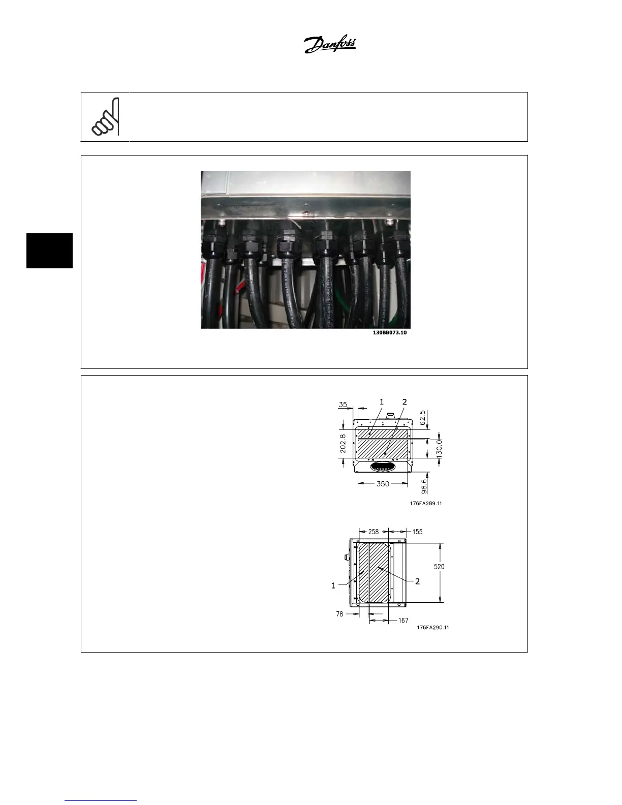
Figure 5.11: Example of proper installation of the gland plate.
Frame size D1 + D2
Frame size E1
Cable entries viewed from the bottom of the adjustable frequency drive - 1) Line power side 2) Motor side
5 How to Install VLT
®
AQUA Drive Design Guide
5-12
MG.20.N5.22 - VLT
®
is a registered Danfoss trademark
5

 Loading...


