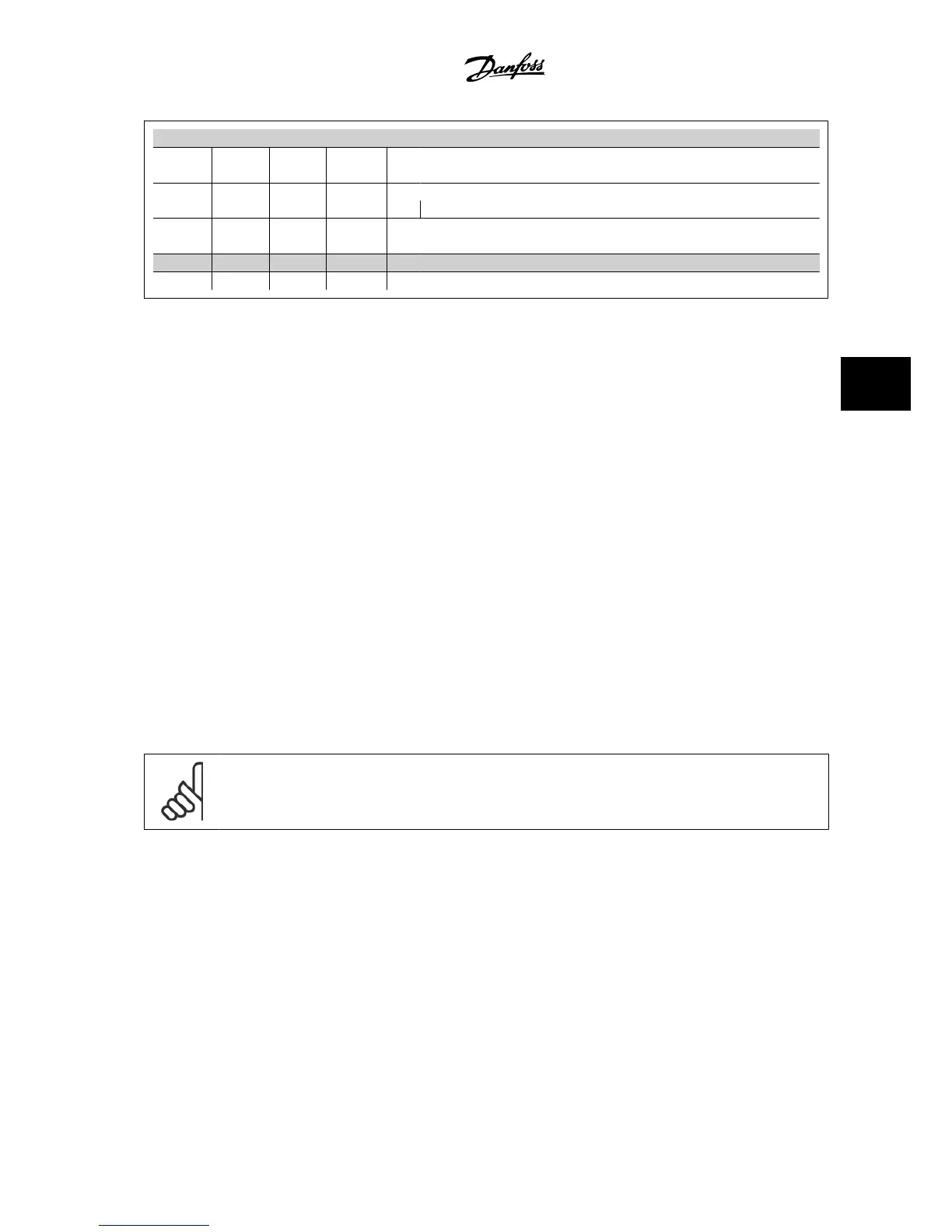
No. 96 97 98 Motor voltage 0–100% of AC line voltage
UVW
3 wires out of motor
U1 V1 W1
6 wires out of motor, Delta-connected
W2 U2 V2
U1 V1 W1 6 wires out of motor, Star-connected
U2, V2, W2 to be interconnected separately
No. 99 Ground connection
PE
5.3.5 Motor Cables
See section General Specifications for correct dimensioning of motor cable cross-section and length.
• Use a shielded/armored motor cable to comply with EMC emission specifications.
• Keep the motor cable as short as possible to reduce the noise level and leakage currents.
• Connect the motor cable shield to both the de-coupling plate of the adjustable frequency drive and to the metal cabinet of the motor.
• Make the shield connections with the largest possible surface area (cable clamp). This is done by using the supplied installation devices in the
adjustable frequency drive.
• Avoid mounting with twisted shield ends (pigtails), which will spoil high frequency shielding effects.
• If it is necessary to split the shield to install a motor isolator or motor relay, the shield must be continued with the lowest possible HF impedance.
F frame Requirements
F1/F3 requirements: Motor phase cable quantities must be 2, 4, 6, or 8 (multiples of 2, 1 cable is not allowed) to obtain equal amount of wires attached
to both inverter module terminals. The cables are required to be equal length within 10% between the inverter module terminals and the first common
point of a phase. The recommended common point is the motor terminals.
F2/F4 requirements: Motor phase cable quantities must be 3, 6, 9, or 12 (multiples of 3, 2 cables are not allowed) to obtain equal amount of wires
attached to each inverter module terminal. The wires are required to be equal length within 10% between the inverter module terminals and the first
common point of a phase. The recommended common point is the motor terminals.
Output junction box requirements: The length, minimum 8 ft [2.5 m], and quantity of cables must be equal from each inverter module to the common
terminal in the junction box.
NOTE!
If a retrofit application requires unequal amount of wires per phase, please consult the factory for requirements.
5.3.6 Electrical Installation of Motor Cables
Shielding of cables
Avoid installation with twisted shield ends (pigtails). They spoil the shielding effect at higher frequencies.
If it is necessary to break the shield to install a motor isolator or motor contactor, the shield must be continued at the lowest possible HF impedance.
Cable length and cross-section
The adjustable frequency drive has been tested with a given length of cable and a given cross-section of that cable. If the cross-section is increased, the
cable capacitance - and thus the leakage current - may increase, thereby requiring that the cable length is reduced accordingly.
VLT
®
AQUA Drive Design Guide 5 How to Install
MG.20.N5.22 - VLT
®
is a registered Danfoss trademark
5-19
5

 Loading...


