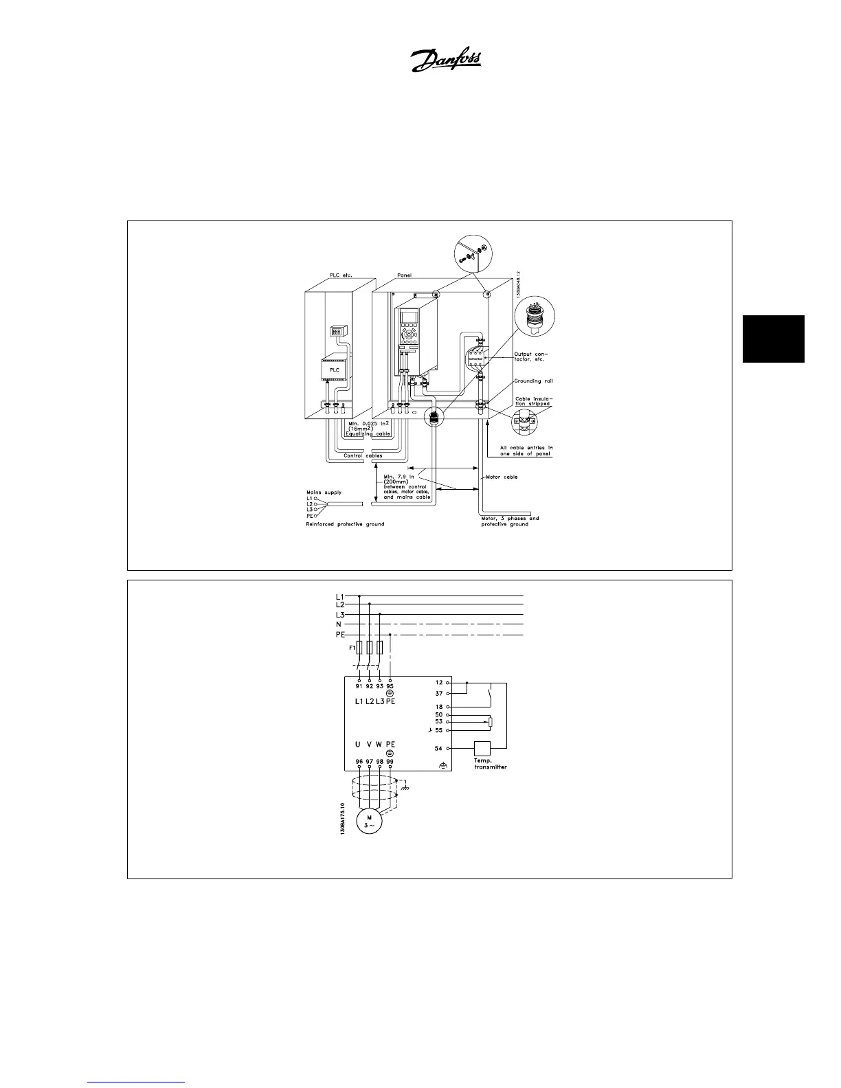
The illustration shows an example of an EMC-correct electrical installation of an IP 20 adjustable frequency drive. The adjustable frequency drive is fitted
in an installation cabinet with an output contactor and connected to a PLC, which is installed in a separate cabinet. Other ways of performing the installation
may result in an equally effective EMC performance, provided the above guidelines for engineering practice are followed.
If the installation is not carried out according to the guidelines, and if non-shielded cables and control wires are used, some emission requirements will
not be fulfilled, although the immunity requirements will be. See the paragraph
EMC test results
.
Figure 5.39: EMC-compliant electrical installation of an adjustable frequency drive in a cabinet.
Figure 5.40: Electrical connection diagram.
VLT
®
AQUA Drive Design Guide 5 How to Install
MG.20.N5.22 - VLT
®
is a registered Danfoss trademark
5-55
5

 Loading...


