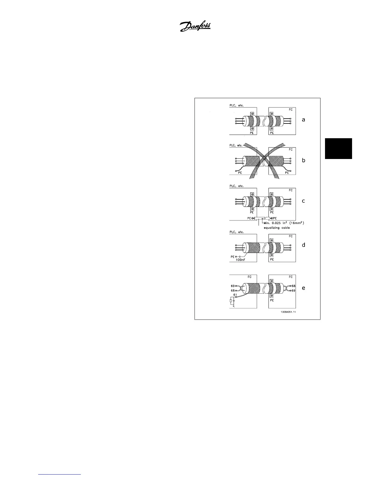
5.11.3 Grounding of Shielded/Armored Control Cables
Generally speaking, control cables must be braided and shielded/armored, and the shield must be connected by means of a cable clamp at both ends to
the metal cabinet of the unit.
The drawing below indicates how correct grounding is carried out and what to do if in doubt.
a. Correct grounding
Control cables and cables for serial communication must be fit-
ted with cable clamps at both ends to ensure the best possible
electrical contact.
b. Wrong grounding
Do not use twisted cable ends (pigtails). They increase the shield
impedance at high frequencies.
c. Protection with respect to ground potential between
PLC and
If the ground potential between the adjustable frequency drive
and the PLC (etc.) is different, electric noise may occur that will
disturb the entire system. Solve this problem by fitting an equal-
izing cable next to the control cable. Minimum cable cross-sec-
tion: 0.025 in
2
[16 mm
2
].
d. For 50/60 Hz ground loops
If very long control cables are used, 50/60 Hz ground loops may
occur. Solve this problem by connecting one end of the shield
to ground via a 100nF capacitor (keeping leads short).
e. Cables for serial communication
Eliminate low-frequency noise currents between two adjustable
frequency drives by connecting one end of the shield to terminal
61. This terminal is grounded via an internal RC link. Use twis-
ted-pair cables to reduce the differential mode interference be-
tween the conductors.
VLT
®
AQUA Drive Design Guide 5 How to Install
MG.20.N5.22 - VLT
®
is a registered Danfoss trademark
5-57
5

 Loading...


