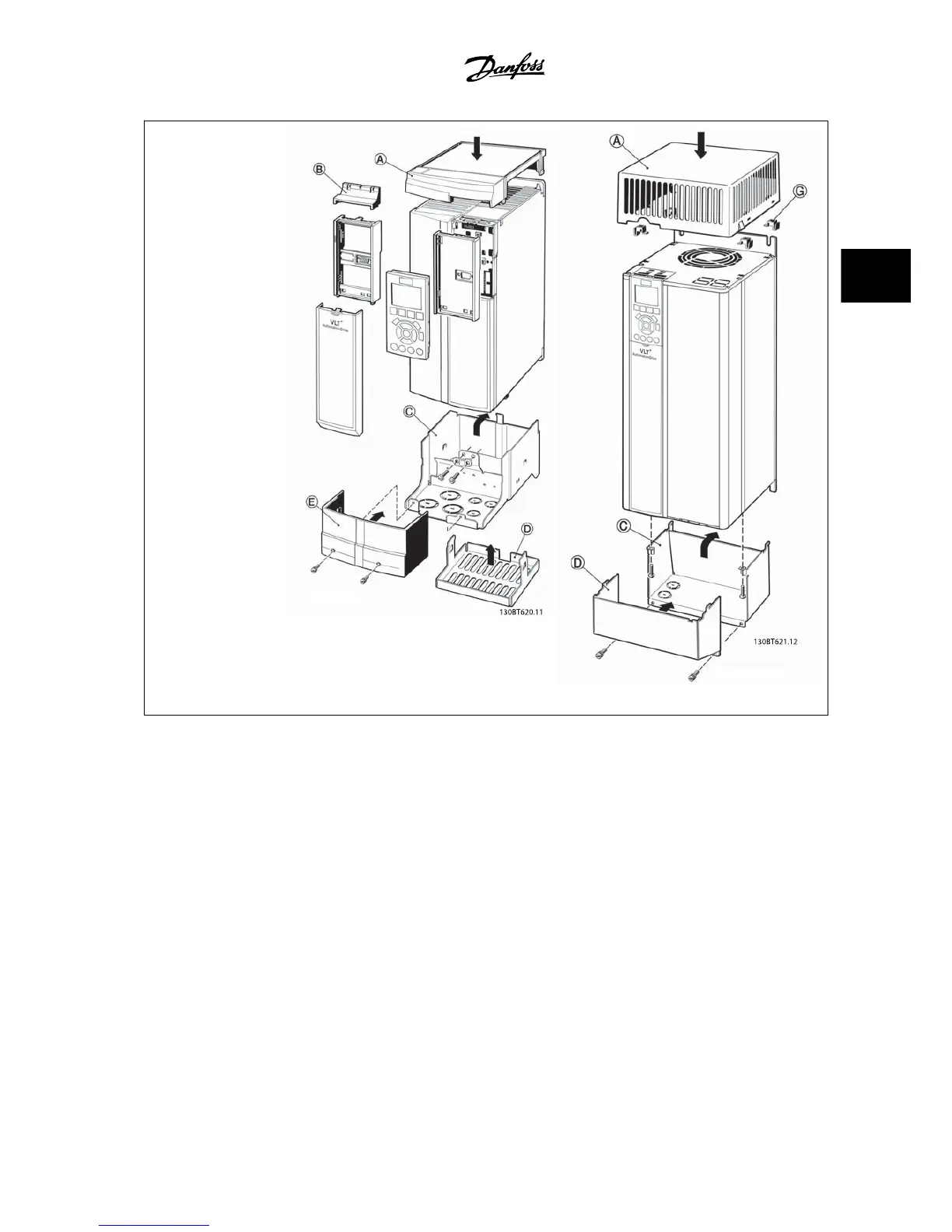
A – Top cover
B – Brim
C – Base part
D – Base cover
E – Screw(s)
F - Fan cover
G - Top clip
When option module A and/
or option module B is/are
used, the brim (B) must be
fitted to the top cover (A).
B3 Enclosure B4 - C3 - C4 Enclosure
3.6.16 Input Filters
Harmonic current distortion is caused by the 6-pulse diode rectifier of the variable speed drive. The harmonic currents are affecting the installed serial
equipment identical to reactive currents. Consequently, harmonic current distortion can result in overheating of the supply transformer, cables, etc.
Depending on the impedance of the power grid, harmonic current distortion can lead to voltage distortion also affecting other equipment powered by
the same transformer. Voltage distortion is increasing losses, causes premature aging and worst of all erratic operation. The majority of harmonics are
reduced by the built-in DC coil but if additional reduction is needed, Danfoss offers two types of passive filters.
The Danfoss AHF 005 and AHF 010 are advanced harmonic filters, not to be compared with traditional harmonic trap filters. The Danfoss harmonic filters
have been specially designed to match the Danfoss adjustable frequency drives.
AHF 010 is reducing the harmonic currents to less than 10% and the AHF 005 is reducing harmonic currents to less than 5% at 2% background distortion
and 2% imbalance.
VLT
®
AQUA Drive Design Guide 3 VLT AQUA Selection
MG.20.N5.22 - VLT
®
is a registered Danfoss trademark
3-45
3
 Loading...


