Frame size UNIT TYPE DIMENSION FOR DISCONNECT TERMINAL
E2
IPOO/CHASSIS A B C D E F
350/450 hp [250/315 kW] (400 V) AND
500/600–675/850 hp [355/450–500/630 KW]
(690 V)
381 (15.0) 245 (9.6) 334 (13.1) 423 (16.7) 256 (10.1) N/A
450/500–550/600 hp [315/355-400/450 kW]
(400 V)
383 (15.1) 244 (9.6) 334 (13.1) 424 (16.7) 109 (4.3) 149 (5.8)
3.3.5 Terminal Locations - frame size F
NOTE!
The F frames have four different sizes, F1, F2, F3 and F4. The F1 and F2 consist of an inverter cabinet on the right and rectifier cabinet
on the left. The F3 and F4 have an additional options cabinet left of the rectifier cabinet. The F3 is an F1 with an additional options
cabinet. The F4 is an F2 with an additional options cabinet.
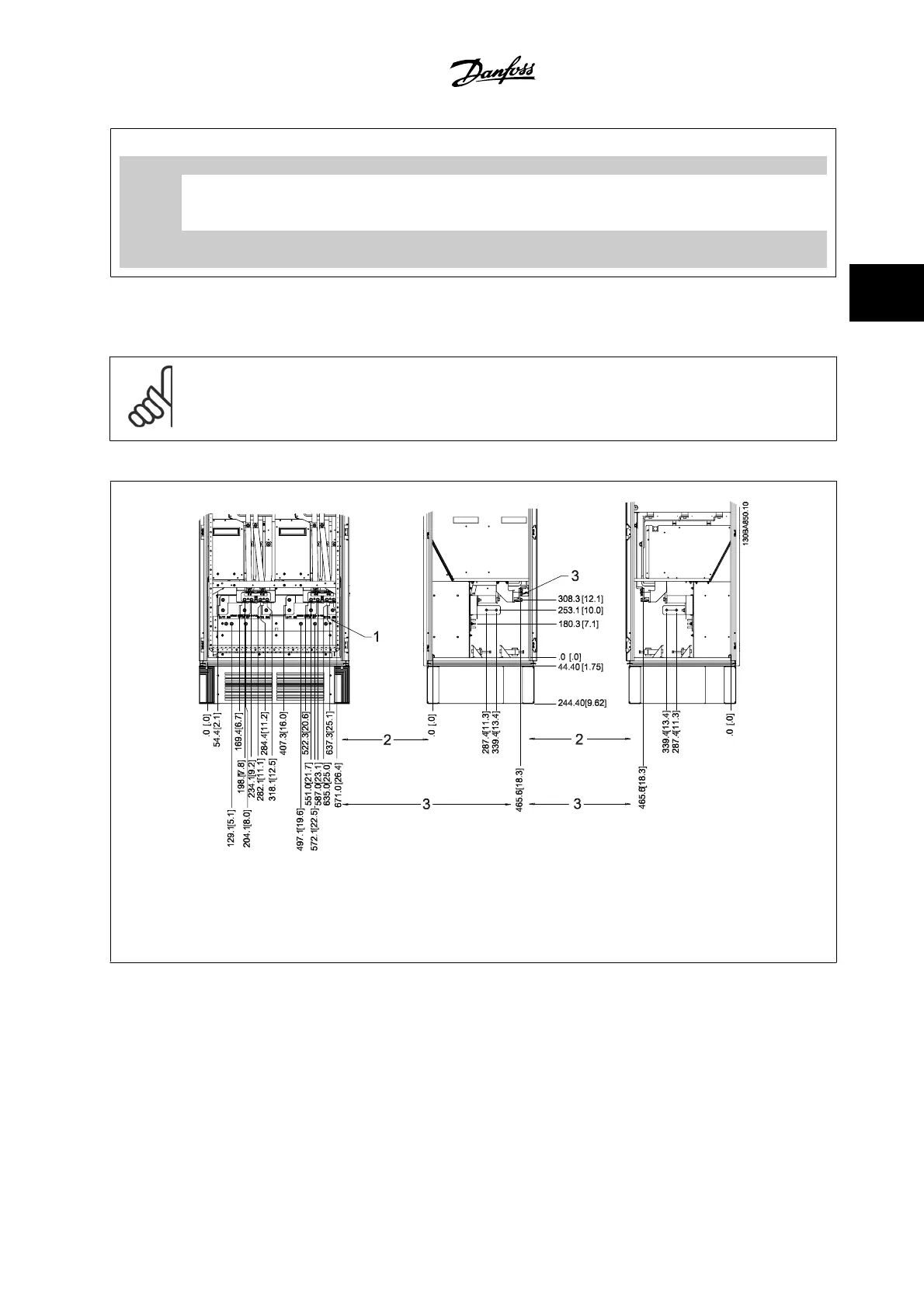
Terminal locations - frame size F1 and F3
Figure 3.19: Terminal locations - Inverter Cabinet - F1 and F3 (front, left and right side view)
1) Earth ground bar
2) Motor terminals
3) Brake terminals
VLT AQUA High Power Instruction Manual 3 How to Install
MG.20.P3.22 - VLT
®
is a registered Danfoss trademark
3-21
3