EasyManuals Logo

Danfoss vlt aqua User Manual

Danfoss vlt aqua
205 pages
To Next Page IconTo Next Page
To Previous Page IconTo Previous Page
Page #36 background imageLoading...
Page #36 background image
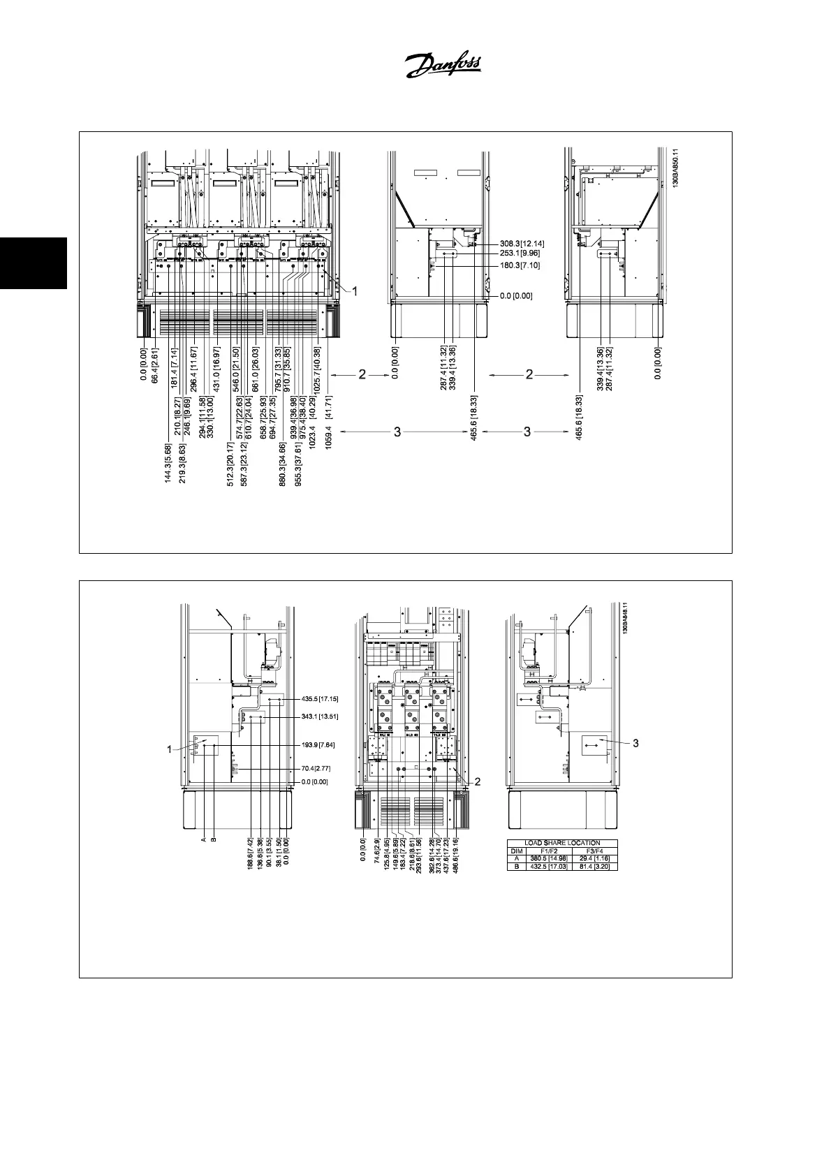
Terminal locations - frame size F2 and F4
Figure 3.20: Terminal locations - Inverter Cabinet - F2 and F4 (front, left and right side view)
1) Earth ground bar
Terminal locations - Rectifier (F1, F2, F3 and F4)
Figure 3.21: Terminal locations - Rectifier (Left side, front and right side view)
1) Load Share Terminal (-)
2) Earth ground bar
3) Load Share Terminal (+)
3 How to Install VLT AQUA High Power Instruction Manual
3-22
MG.20.P3.22 - VLT
®
is a registered Danfoss trademark
3

Other manuals for Danfoss vlt aqua

Questions and Answers:

Question and Answer IconNeed help?

Do you have a question about the Danfoss vlt aqua and is the answer not in the manual?

Danfoss vlt aqua Specifications

General IconGeneral
Supply Voltage200-240V, 380-500V, 525-600V
EnclosureIP20
FeaturesEnergy optimization
ApprovalsCE, UL, cUL
Input Voltage Range200-240V, 380-500V, 525-600V
Output Voltage Range0 to supply voltage
Protection FeaturesOvervoltage, Undervoltage, Overcurrent, Short circuit, Ground fault
Communication InterfacesPROFIBUS
Cooling MethodAir-cooled

Related product manuals