3.6.7 Motor cable
The motor must be connected to terminals U/T1/96, V/T2/97, W/T3/98. Ground to terminal 99. All types of three-phase asynchronous standard motors
can be used with an adjustable frequency drive unit. The factory setting is for clockwise rotation with the adjustable frequency drive output connected
as follows:
Terminal No.
Function
96, 97, 98, 99 Line power U/T1, V/T2, W/T3
Ground
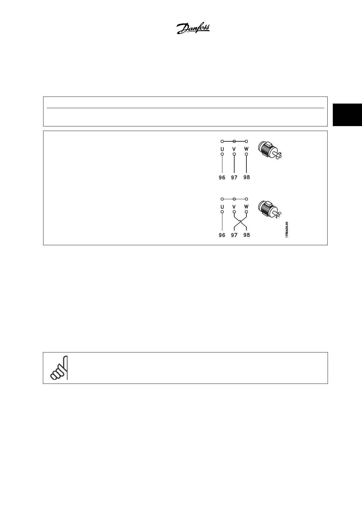
• Terminal U/T1/96 connected to U-phase
• Terminal V/T2/97 connected to V-phase
• Terminal W/T3/98 connected to W-phase
The direction of rotation can be changed by switching two phases in the motor cable or by changing the setting of par. 4-10
Motor Speed Direction
.
Motor rotation check can be performed using par. 1-28
Motor Rotation Check
and following the steps shown in the display.
F frame Requirements
F1/F3 requirements: Motor phase cable quantities must be 2, 4, 6, or 8 (multiples of 2, 1 cable is not allowed) to obtain equal amount of wires attached
to both inverter module terminals. The cables are required to be equal length within 10% between the inverter module terminals and the first common
point of a phase. The recommended common point is the motor terminals.
F2/F4 requirements: Motor phase cable quantities must be 3, 6, 9, or 12 (multiples of 3, 2 cables are not allowed) to obtain equal amount of wires
attached to each inverter module terminal. The wires are required to be equal length within 10% between the inverter module terminals and the first
common point of a phase. The recommended common point is the motor terminals.
Output junction box requirements: The length, minimum 8 ft [2.5 m], and quantity of cables must be equal from each inverter module to the common
terminal in the junction box.
NOTE!
If a retrofit application requires unequal amount of wires per phase, please consult the factory for requirements.
VLT AQUA High Power Instruction Manual 3 How to Install
MG.20.P3.22 - VLT
®
is a registered Danfoss trademark
3-55
3