3.6.8 Brake Cable Drives with factory-installed brake chopper option
(Only standard with letter B in position 18 of typecode).
The connection cable to the brake resistor must be shielded and the max. length from the adjustable frequency drive to the DC bar is limited to 82 feet
[25 m].
Terminal No.
Function
81, 82 Brake resistor terminals
The connection cable to the brake resistor must be shielded. Connect the shield by means of cable clamps to the conductive backplate at the adjustable
frequency drive and to the metal cabinet of the brake resistor.
Size the brake cable cross-section to match the brake torque. See also
Brake Instructions, MI.90.Fx.yy
and
MI.50.Sx.yy
for further information regarding
safe installation.
Please note that voltages up to 1099 V DC, depending on the supply voltage, may occur on the terminals.
F Frame Requirements
The brake resistor(s) must be connected to the brake terminals in each inverter module.
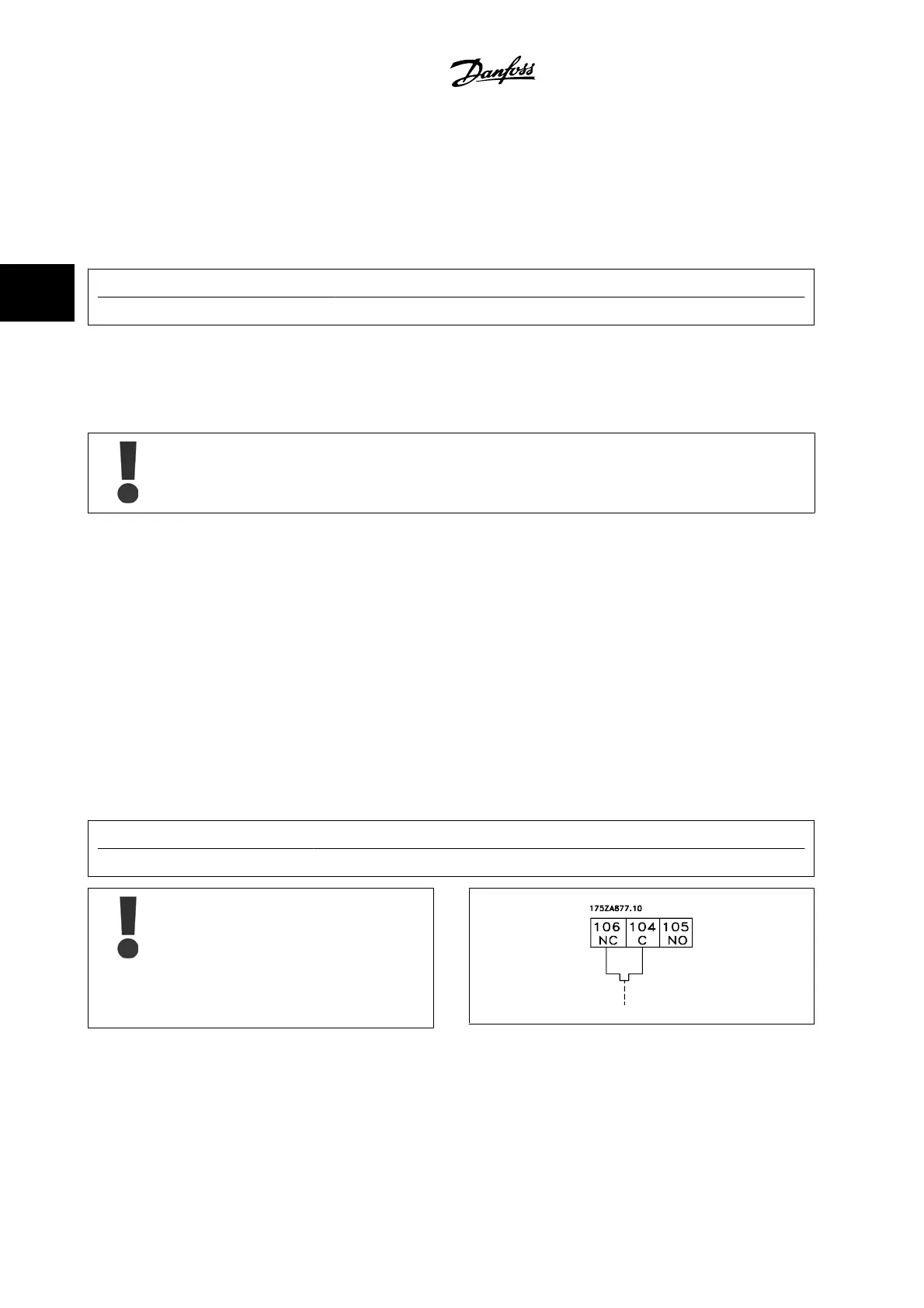
3.6.9 Brake Resistor Temperature Switch
Torque: 0.5–0.6 Nm (5 in-lbs)
Screw size: M3
This input can be used to monitor the temperature of an externally connected brake resistor. If the input between 104 and 106 is established, the
adjustable frequency drive will trip on warning / alarm 27, “Brake IGBT”. If the connection is closed between 104 and 105, the adjustable frequency drive
will trip on warning/alarm 27, “Brake IGBT”.
Normally closed: 104-106 (factory-installed jumper)
Normally open: 104-105
Terminal No.
Function
106, 104, 105 Brake resistor temperature switch.
If the temperature of the brake resistor gets too high
and the thermal switch drops out, the adjustable fre-
quency drive will stop braking. The motor will start
coasting.
A KLIXON switch must be installed that is 'normally
closed'. If this function is not used, 106 and 104 must
be short-circuited together.
3 How to Install VLT AQUA High Power Instruction Manual
3-56
MG.20.P3.22 - VLT
®
is a registered Danfoss trademark
3