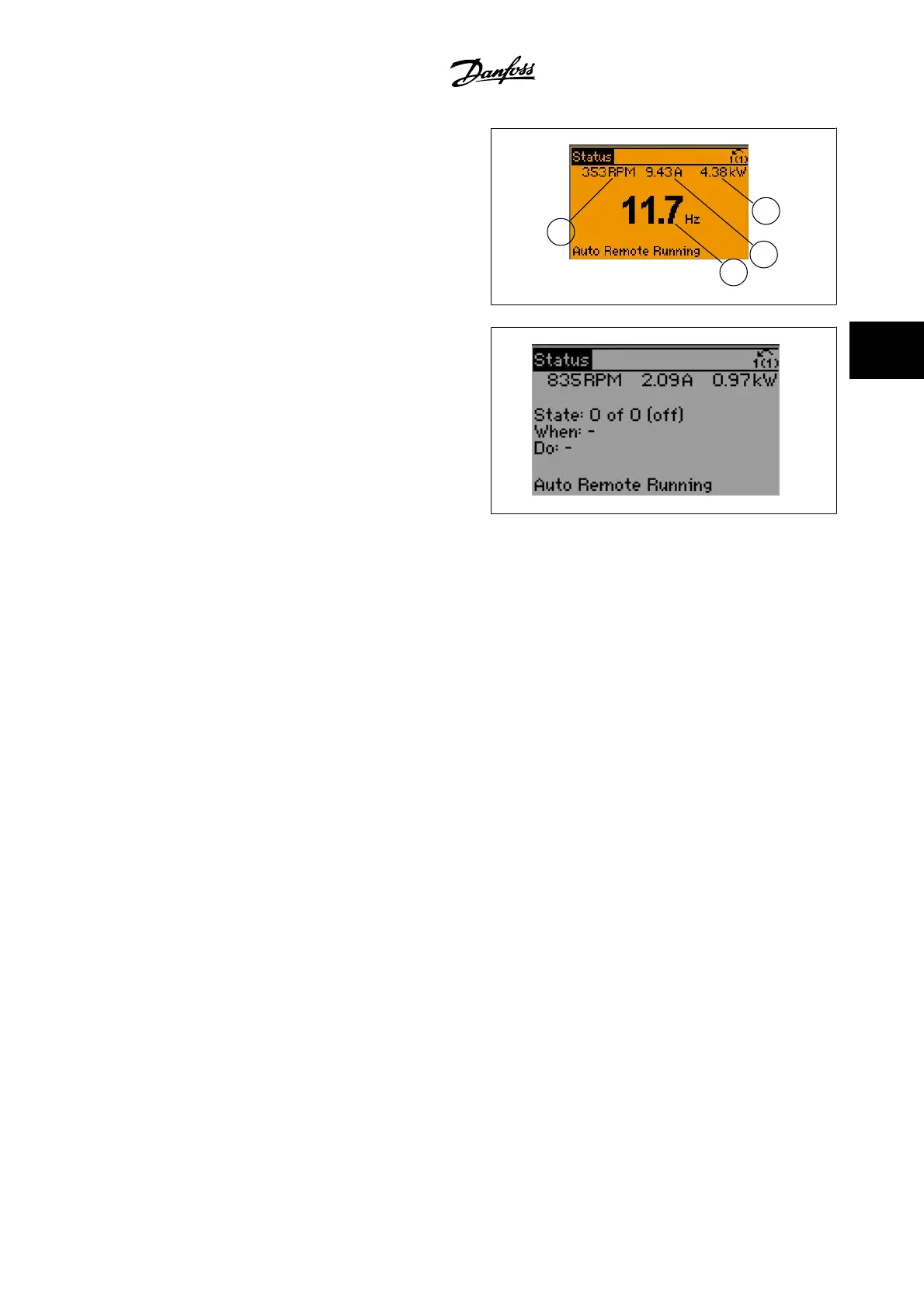
Status display II
See the operating variables (1.1, 1.2, 1.3 and 2) shown in the display in
this illustration.
In the example, Speed, Motor current, Motor power and Frequency are
selected as variables in the first and second lines.
1.1, 1.2 and 1.3 are shown in small size, while 2 is shown in large size.
1
3
0
B
P
0
6
2
.
1
0
1.1
1.3
1.2
2
Status display III:
This state displays the event and action of the smart logic control. For
further information, see the section
Smart Logic Control
.
1
3
0
B
P
0
6
3
.
1
0
VLT AQUA High Power Instruction Manual
4 How to operate the adjustable frequency
drive
MG.20.P3.22 - VLT
®
is a registered Danfoss trademark
4-3
4