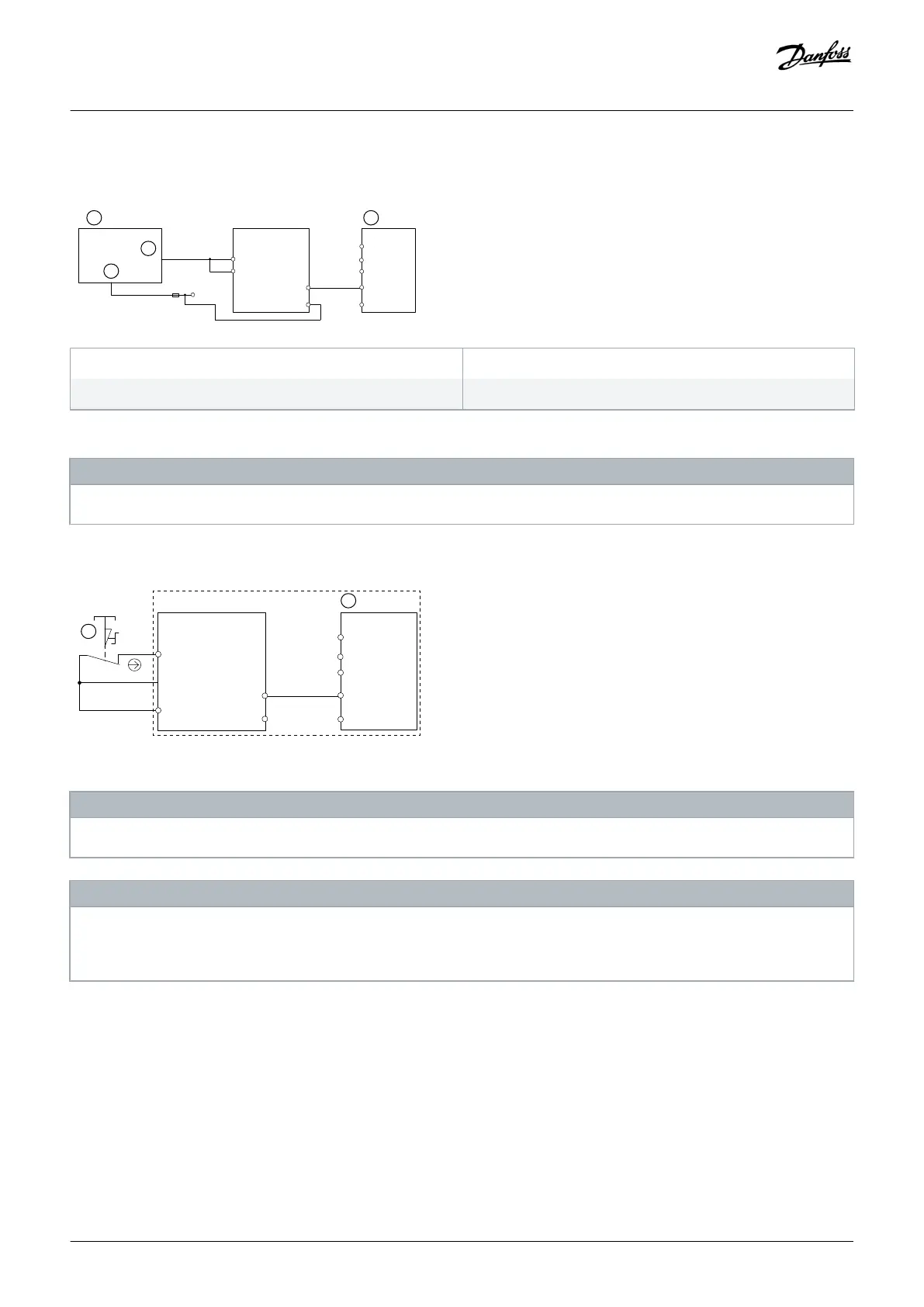
Connecting a digital output module
A Safety PLC
C GND
B Safety output
D Drive
Illustration 32: Connecting a Digital Output Module, for Example Safety PLC
N O T I C E
The safety level is downgraded when inputs are used a 1 channel only.
Connecting a sensor, for example a 1-channel emergency stop push button
Illustration 33: Connecting a Sensor, for Example 1-channel Emergency Stop Mushroom Push Button or Limit Switch
N O T I C E
All equipment used must be suitable for the selected category/PL or SIL.
N O T I C E
Use of a 1-channel E-stop switch provides no input redundancy and no ability for the safety option to monitor for input short
circuits. One-channel E-stop switches used with a safety option are suitable only for category 2 applications, per EN ISO 13849-1
PL c or SIL1.
When a 1-channel E-stop is used, guard against failure modes that can result in an unsafe condition. An example of an unsafe condition
could be the failure of the contact to a short circuit condition. A switch with positive opening operation should be used to reduce the
possibility of a failure of the switch to open. A short-circuit failure results in loss of switching function. This failure can occur from a
short across the switch contacts, a short across the wires connected to the switch between the switch and the safety option, or a short
to a secondary source of power. To reduce these risks, physically separate the wires from each other and from other sources of power
(for example, in separate wire ways or conduit). According to the definition of European standard EN ISO 13849-1, a 1-channel E-stop
could be used in applications where PL c or less (b or a) has been determined via a risk-assessment procedure.
Application Examples
Installation Guide | VLT®Safety Option MCB 152
AN327351953089en-000101 / 130R0578| 55
Danfoss A/S © 2020.02

 Loading...


