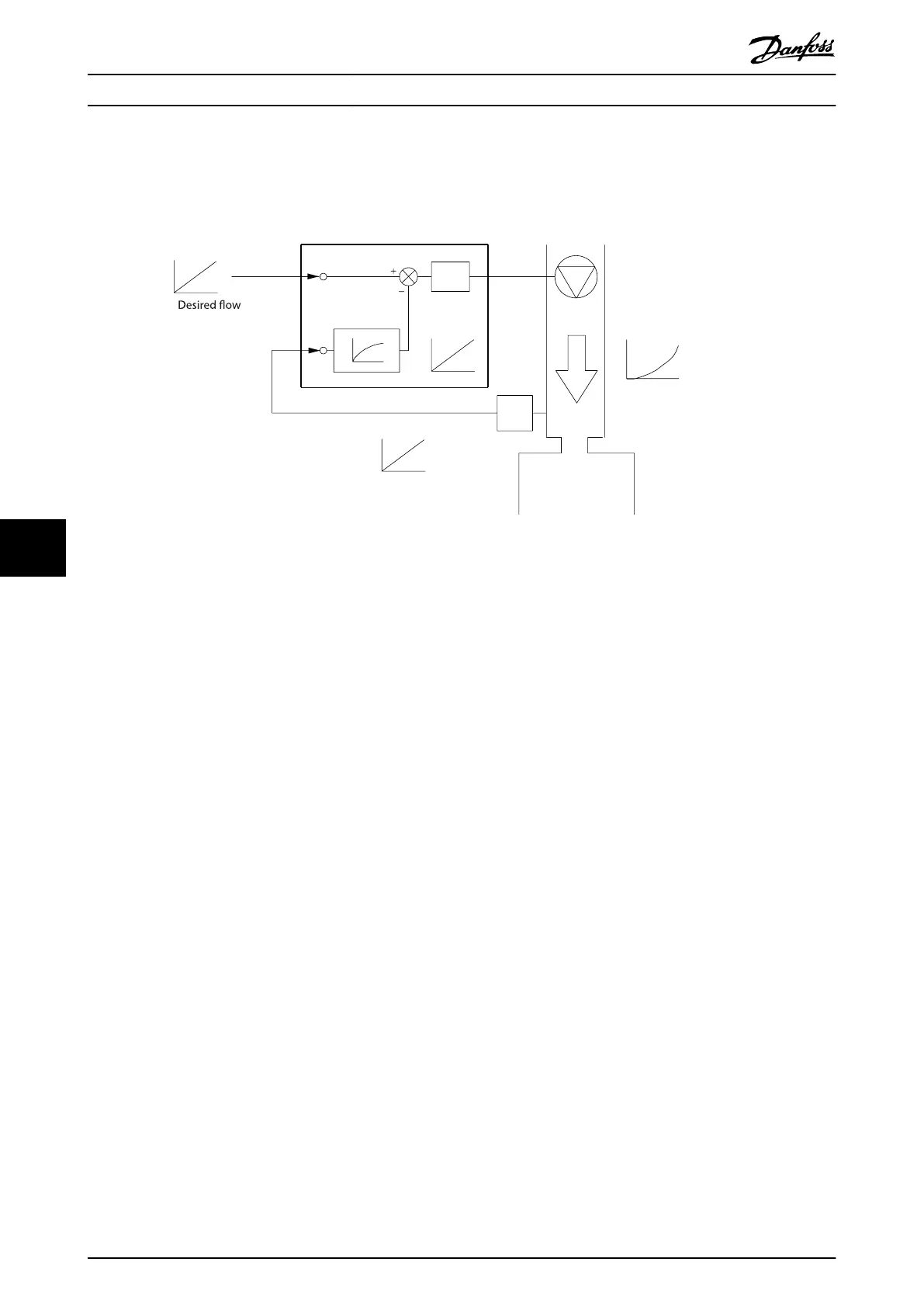
Feedback conversion
In some applications, it is useful to convert the feedback signal. One example is using a pressure signal to provide ow
feedback. Since the square root of pressure is proportional to ow, the square root of the pressure signal yields a value
proportional to the ow, see Illustration 8.5.
130BF834.10
Reference signal
Reference
FB conversion
FB signal
P
Flow
FB
P
Flow
PID
P
Parameter 20-01
Parameter 20-04
Parameter 20-07
Illustration 8.5 Feedback Conversion
8.2.4 Control Structure Overview
The control structure is a software process that controls the motor based on user-dened references (for example, RPM) and
whether feedback is used/not used (closed loop/open loop). The operator denes the control in parameter 1-00 Congu-
ration Mode.
The control structures are as follows:
Open-loop control structure
•
Speed (RPM).
•
Torque (Nm).
Closed-loop control structure
•
Speed (RPM).
•
Torque (Nm).
•
Process
(user-dened units, for example, feet, lpm, psi, %, bar).
Basic Operating Principles ... VLT® AutomationDrive FC 361
64 Danfoss A/S © 03/2019 All rights reserved. MG06K102
88
 Loading...


