8.2.3 Feedback Handling
Feedback handling can be congured to work with applications requiring advanced control, such as multiple setpoints and
multiple types of feedback. See Illustration 8.4. Three types of control are common:
Single zone (single setpoint)
This control type is a basic feedback conguration. Setpoint 1 is added to any other reference (if any) and the feedback
signal is selected.
Multi-zone (single setpoint)
This control type uses 2 or 3 feedback sensors but only 1 setpoint. The feedback can be added, subtracted, or averaged. In
addition, the maximum or minimum value can be used. Setpoint 1 is used exclusively in this conguration.
Multi-zone (setpoint/feedback)
The setpoint/feedback pair with the largest dierence controls the speed of the drive. The maximum value attempts to keep
all zones at or below their respective setpoints, while the minimum value attempts to keep all zones at or above their
respective setpoints.
Example
A 2-zone, 2-setpoint application. Zone 1 setpoint is 15 bar, and the feedback is 5.5 bar. Zone 2 setpoint is 4.4 bar, and the
feedback is 4.6 bar. If maximum is selected, the zone 2 setpoint and feedback are sent to the PID controller, since it has the
smaller dierence (feedback is higher than setpoint, resulting in a negative dierence). If minimum is selected, the zone 1
setpoint and feedback is sent to the PID controller, since it has the larger dierence (feedback is lower than setpoint,
resulting in a positive dierence).
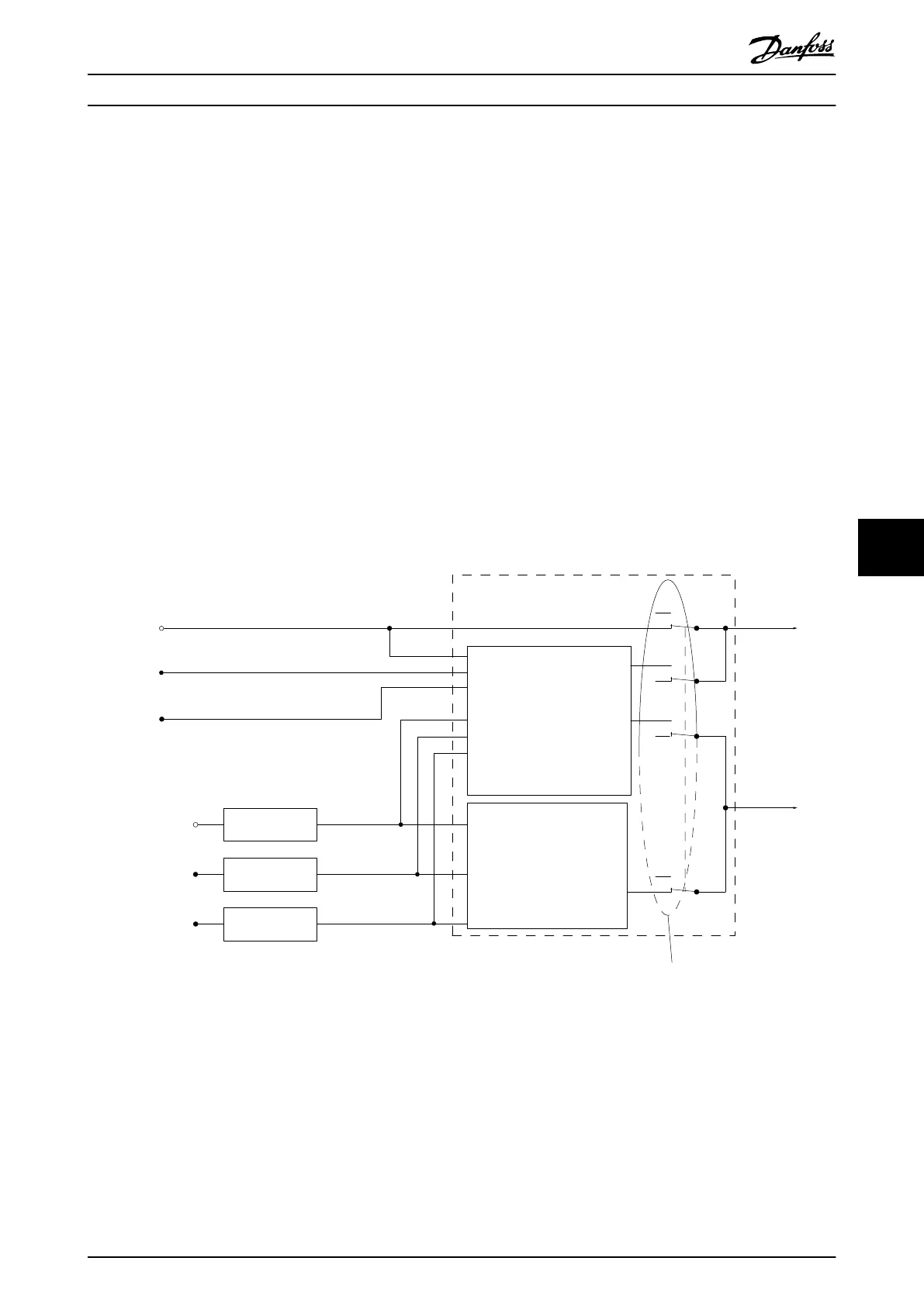
Setpoint 1
P 20-21
Setpoint 2
P 20-22
Setpoint 3
P 20-23
Feedback 1 Source
P 20-00
Feedback 2 Source
P 20-03
Feedback 3 Source
P 20-06
Feedback conv.
P 20-01
Feedback conv.
P 20-04
Feedback conv.
P 20-07
Feedback 1
Feedback 2
Feedback 3
Feedback
Feedback Function
P 20-20
Multi setpoint min.
Multi setpoint max.
Feedback 1 only
Feedback 2 only
Feedback 3 only
Sum (1+2+3)
Dierence (1-2)
Average (1+2+3)
Minimum (1|2|3)
Maximum (1|2|3)
Setpoint to
Reference
Handling
0%
0%
0%
0%
130BA354.12
Illustration 8.4 Block Diagram of Feedback Signal Processing
Basic Operating Principles ... Design Guide
MG06K102 Danfoss A/S © 03/2019 All rights reserved. 63
8 8
 Loading...


