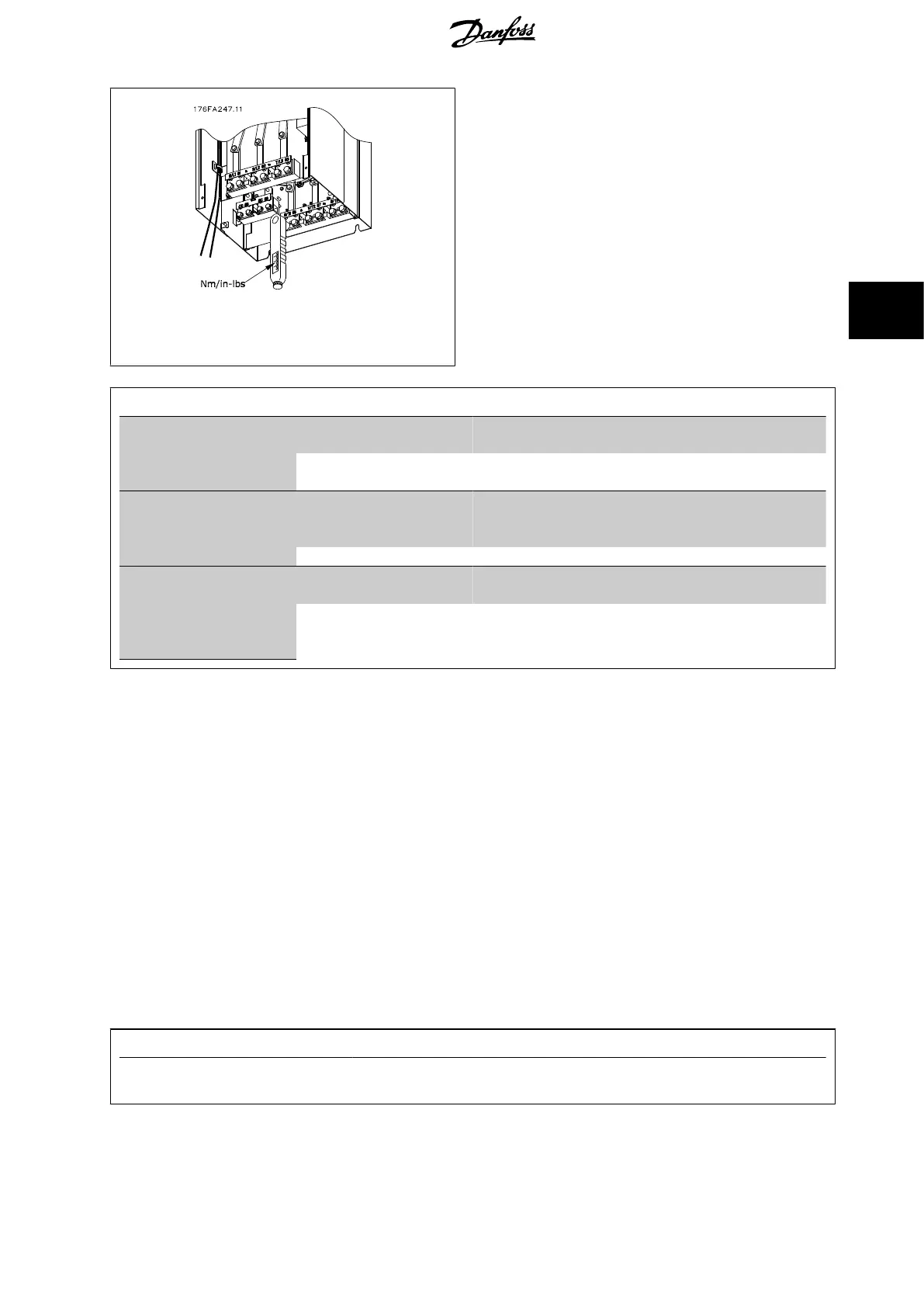
Illustration 4.33: Always use a torque wrench to tighten the
bolts.
Frame size Terminal Torque Bolt size
D Mains
Motor
19-40 Nm (168-354 in-lbs) M10
Load sharing
Brake
8.5-20.5 Nm (75-181 in-lbs) M8
E Mains
Motor
Load sharing
19-40 Nm (168-354 in-lbs) M10
Brake 8.5-20.5 Nm (75-181 in-lbs) M8
F Mains
Motor
19-40 Nm (168-354 in-lbs) M10
Load sharing
Brake
Regen
19-40 Nm (168-354 in-lbs)
8.5-20.5 Nm (75-181 in-lbs)
8.5-20.5 Nm (75-181 in-lbs)
M10
M8
M8
Table 4.2: Torque for terminals
4.6.6 Shielded Cables
It is important that shielded and armoured cables are connected in a proper way to ensure high EMC immunity and low emissions.
Connection can be made using either cable glands or clamps:
• EMC cable glands: Generally available cable glands can be used to ensure an optimum EMC connection.
• EMC cable clamp: Clamps allowing easy connection are supplied with the frequency converter.
4.6.7 Motor Cable
The motor must be connected to terminals U/T1/96, V/T2/97, W/T3/98 located on the far right of the unit. Earth to terminal 99. All types of three-phase
asynchronous standard motors can be used with a frequency converter unit. The factory setting is for clockwise rotation with the frequency converter
output connected as follows:
Terminal No. Function
96, 97, 98, 99 Mains U/T1, V/T2, W/T3
Earth
VLT HVAC Low Harmonic Drive Operating In-
structions 4 How to Install
MG.16.A1.02 - VLT
®
is a registered Danfoss trademark 51
4

 Loading...


