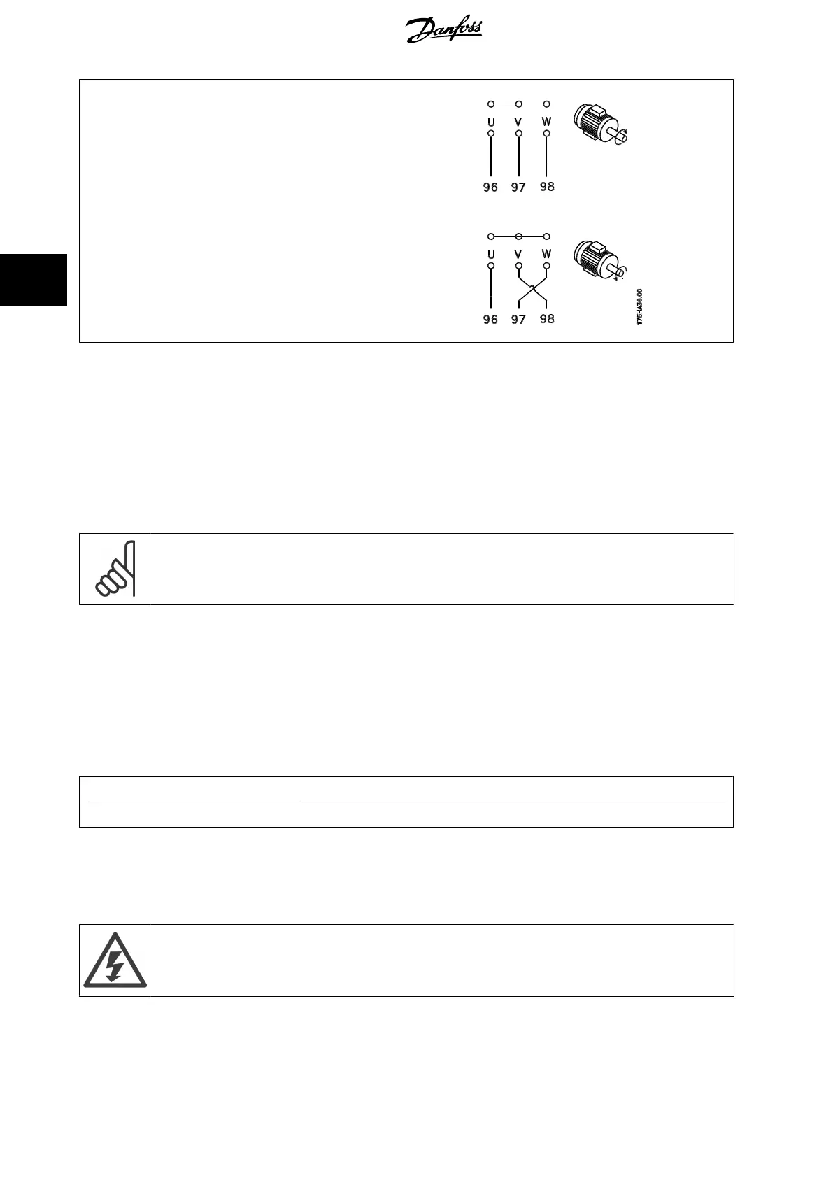
• Terminal U/T1/96 connected to U-phase
• Terminal V/T2/97 connected to V-phase
• Terminal W/T3/98 connected to W-phase
The direction of rotation can be changed by switching two phases in the motor cable or by changing the setting of par. 4-10
Motor Speed Direction
.
Motor rotation check can be performed using par. 1-28
Motor Rotation Check
and following the steps shown in the display.
F frame Requirements
Motor phase cable quantities must be multiples of 2, resulting in 2, 4, 6, or 8 (1 cable is not allowed) to obtain equal amount of wires attached to both
inverter module terminals. The cables are required to be equal length within 10% between the inverter module terminals and the first common point of
a phase. The recommended common point is the motor terminals.
Output junction box requirements: The length, minimum 2.5 meters, and quantity of cables must be equal from each inverter module to the common
terminal in the junction box.
NB!
If a retrofit applications requires unequal amount of wires per phase please consult the factory for requirements and documentation
or use the top/bottom entry side cabinet option, instruction 177R0097.
4.6.8 Brake Cable Drives with Factory Installed Brake Chopper Option
(Only standard with letter B in position 18 of typecode).
The connection cable to the brake resistor must be screened and the max. length from frequency converter to the DC bar is limited to 25 metres (82
feet).
Terminal No. Function
81, 82 Brake resistor terminals
The connection cable to the brake resistor must be screened. Connect the screen by means of cable clamps to the conductive back plate at the frequency
converter and to the metal cabinet of the brake resistor.
Size the brake cable cross-section to match the brake torque. See also
Brake Instructions, MI.90.Fx.yy
and
MI.50.Sx.yy
for further information regarding
safe installation.
Please note that voltages up to 790 VDC, depending on the supply voltage, may occur on the terminals.
F Frame Requirements
The brake resistor(s) must be connected to the brake terminals in each inverter module.
4 How to Install
VLT HVAC Low Harmonic Drive Operating In-
structions
52 MG.16.A1.02 - VLT
®
is a registered Danfoss trademark
4

 Loading...


