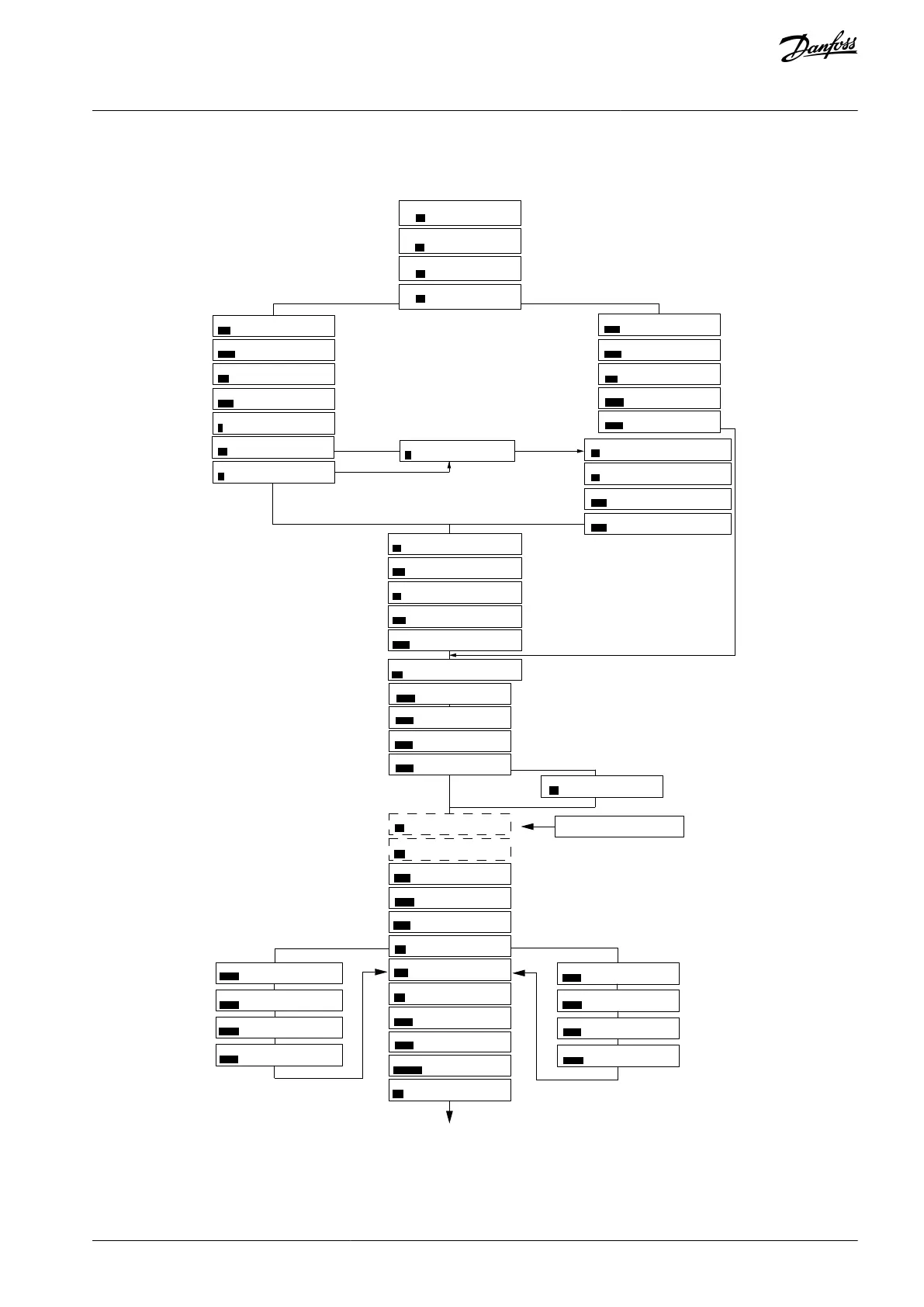
3.2.2.4 Setup Wizard for Closed-loop Applications
6-29 Terminal 54 Mode
[1]
Voltage
6-25 T54 high Feedback
0050
Hz
20-94 PI integral time
0020.00
s
Current
Voltage
This dialog is forced to be set to
[1] Analog input 54
20-00 Feedback 1 source
[1]
Analog input 54
3-10 Preset reference [0]
0.00
3-03 Max Reference
50.00
3-02 Min Reference
0.00
Induction motor
1-24 Motor Current
04.66
A
3-41 Ramp 1 ramp-up time
0010
s
3-42 Ramp1 ramp-down time
0010
s
4-12 Motor speed low limit
0016
Hz
4-14 Motor speed high limit
0050
Hz
6-22 T54 Low Current
A
6-24 T54 low Feedback
0016
Hz
6-23 T54 high Current
13.30
A
6-25 T54 high Feedback
0050
0.01
s
20-81 PI Normal/Inverse Control
[0]
Normal
20-83 PI Normal/Inverse Control
0050
Hz
20-93 PI Proportional Gain
00.50
1-29 Automatic Motor Adaption
[0]
Off
6-20 T54 low Voltage
0050
V
6-24 T54 low Feedback
0016
Hz
6-21 T54 high Voltage
0220
V
6-26
T54 Filter time const.
3-16 Reference Source 2
[0]
No Operation
[0]
200-240V/50Hz/Delta
1-30 Stator Resistance
0.65
Ohms
1-25 Motor Nominal Speed
3000
RPM
1-24 Motor Current
3.8
A
1-26 Motor Cont. Rated Torque
5.4
Nm
1-38 q-axis inductance(Lq)
5
mH
4-19 Max Ouput Frequency
0065
Hz
1-40 Back EMF at 1000 RPM
57
V
PM motor
1-39 Motor Poles
04.66
Hz
Motor type = Induction
Motor type = PM motor
Motor type = IPM
Motor type = SPM
1-44 d-axis Inductance Sat. (LdSat)
(1-70) Start Mode
Rotor Detection
[0]
1-46 Position Detection Gain
%
Off
100
30-22 Locked Rotor Detection
[0]
s
30-23 Locked Rotor Detection Time[s]
0.10
5
mH
1-42 Motor Cable Length
50
m
(1-45) q-axis Inductance Sat. (LqSat)
(1-48) Current at Min Inductanc e for d-axis
100
%
1-49 Current at Min Inductanc e for q-axis
%
1-37 d-axis inductance(Lq)
5
mH
Illustration 5: Setup Wizard for Closed-loop Applications
AU363928304090en-000101 / 130R0982 | 17Danfoss A/S © 2021.07
Programming
VLT® Flow Drive FC 111
Programming Guide
 Loading...


