4.9.7 8-9* Bus Feedback
8-94 Bus Feedback 1
Change during operation: True
Write feedback to this parameter via the serial communication port. Select this parameter in parameter 20-00 Feedback 1 Source as a
feedback source. Hex value 4000 h corresponds to 100% feedback/range is ±200%.
Table 216: Range:
8-95 Bus Feedback 2
Change during operation: True
This parameter allows setting of a bus feedback value via the serial communication port or options which forms part of the feed-
back handling. Bus Feedback may be chosen as feedback source.
Table 217: Range:
4.10 Parameter Group 13-** Smart Logic
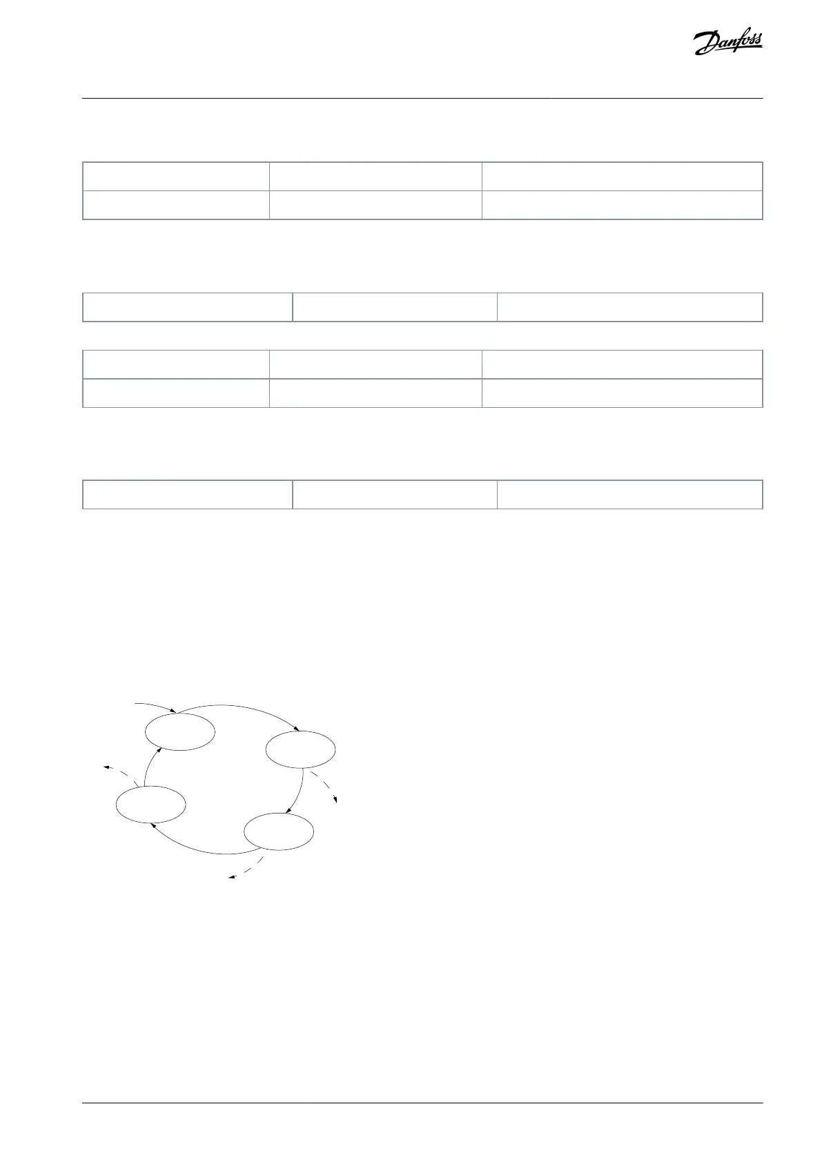
Smart logic control (SLC) is a sequence of user-defined actions (see parameter 13-52 SL Controller Action [x]) executed by the SLC
when the SLC evaluates the associated user-defined event (see parameter 13-51 SL Controller Event [x]) as true. Events and actions
are each numbered and linked in pairs. This means that when [0] event is fulfilled (attains the value true), [0] action is executed.
After executing this action, the conditions of [1] event is evaluated. If it is evaluated as true, [1] action is executed, and so on. Only 1
event is evaluated at any time. If an event is evaluated as false, nothing happens (in the SLC) during the current scan interval and no
other events are evaluated. This means that when the SLC starts, it evaluates [0] event (and only [0] event) each scan interval. Only
when [0] event is evaluated as true, the SLC executes [0] action and starts evaluating [1] event. It is possible to program from 1–20
events and actions. When the last event/action has been executed, the sequence starts over again from [0] event/[0] action.
e30ba062.15
State 1
13-51.0
13-52.0
State 2
13-51.1
13-52.1
Start
event P13-01
State 3
13-51.2
13-52.2
State 4
13-51.3
13-52.3
Stop
event P13-02
Stop
event P13-02
Stop
event P13-02
Illustration 15: Example with 3 Event/Actions
Starting and stopping the SLC
To start or stop the SLC, select [1] On or [2] Off in parameter 13-00 SL Controller Mode. The SLC always starts in state 0 (where it
evaluates [0] event). The SLC starts when the start event (defined in parameter 13-01 Start Event) is evaluated as true (if [1] On is
selected in parameter 13-00 SL Controller Mode). The SLC stops when the stop event (parameter 13-02 Stop Event) is true. Parameter
13-03 Reset SLC resets all SLC parameters and starts programming from the beginning.
4.10.1 13-0* SLC Settings
To activate, deactivate, and reset the smart logic control sequence, use the SLC settings. The logic functions and comparators are
always running in the background, which opens for separate control of digital inputs and outputs.
AU363928304090en-000101 / 130R0982 | 115Danfoss A/S © 2021.07
Parameters
VLT® Flow Drive FC 111
Programming Guide
 Loading...


