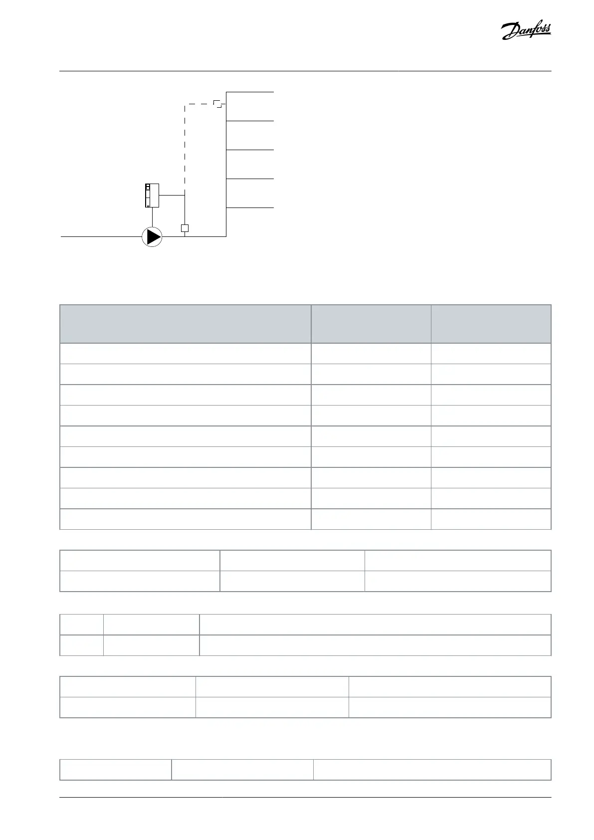
Illustration 19: Flow Compensation Set-up
There are 2 methods which can be employed, depending on whether the speed at system design working point is known.
Table 409: Speed at Design Point Known/Unknown
Speed at design point
KNOWN
Speed at design point
UNKNOWN
Parameter 22-80 Flow Compensation
Parameter 22-81 Square-linear Curve Approximation
Parameter 22-82 Work Point Calculation
Parameter 22-84 Speed at No-Flow [Hz]
Parameter 22-86 Speed at Design Point [Hz]
Parameter 22-87 Pressure at No-Flow Speed
Parameter 22-88 Pressure at Rated Speed
Parameter 22-89 Flow at Design Point
Parameter 22-90 Flow at Rated Speed
22-80 Flow Compensation
Default value: [0] Disabled
Change during operation: True
Table 410: Option:
Disable flow compensation of setpoint.
Enable flow compensation of setpoint.
22-81 Square-linear Curve Approximation
Change during operation: True
Adjust shape of control curve. 0% = straight line, 100% = maximum parabola.
Table 411: Range:
AU363928304090en-000101 / 130R0982 | 175Danfoss A/S © 2021.07
Parameters
VLT® Flow Drive FC 111
Programming Guide
 Loading...


