Table 144: Range:
4.7.5 5-5* Pulse Input
The pulse input parameters are used to define an appropriate window for the impulse reference area by configuring the scaling and
filter settings for the pulse inputs. Input terminals 29 act as frequency reference inputs. Set terminal 29 (parameter 5-13 Terminal 29
Digital Input) to [32] Pulse input. If terminal 29 is used as an input, set parameter 5-02 Terminal 29 Mode to [0] Input.
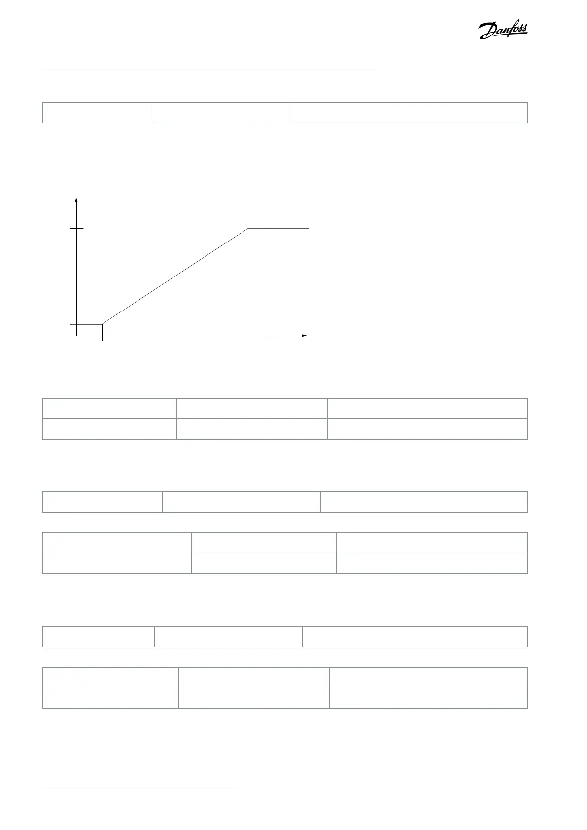
e30bu896.10
(RPM)
Ref.
Low freq.
P 5-50
Input
(Hz)
High
ref.
value
P 5-53
High freq.
P 5-51
Low
ref.
value
P 5-52
Illustration 14: Pulse Input
5-50 Term. 29 Low Frequency
Change during operation: True
Enter the low frequency limit corresponding to the low motor shaft speed (that is low reference value) in parameter 5-52 Term. 29
Low Ref./Feedb. Value.
Table 145: Range:
5-51 Term. 29 High Frequency
Change during operation: True
Enter the high frequency limit corresponding to the high motor shaft speed (that is high reference value) in parameter 5-53 Term. 29
High Ref./Feedb. Value.
Table 146: Range:
5-52 Term. 29 Low Ref./Feedb. Value
Change during operation: True
Enter the reference or feedback value (in for example, RPM, Hz, bar) that corresponds to the pulse frequency set in parameter 5-50
Term. 29 Low Frequency.
AU363928304090en-000101 / 130R098290 | Danfoss A/S © 2021.07
Parameters
VLT® Flow Drive FC 111
Programming Guide
 Loading...


