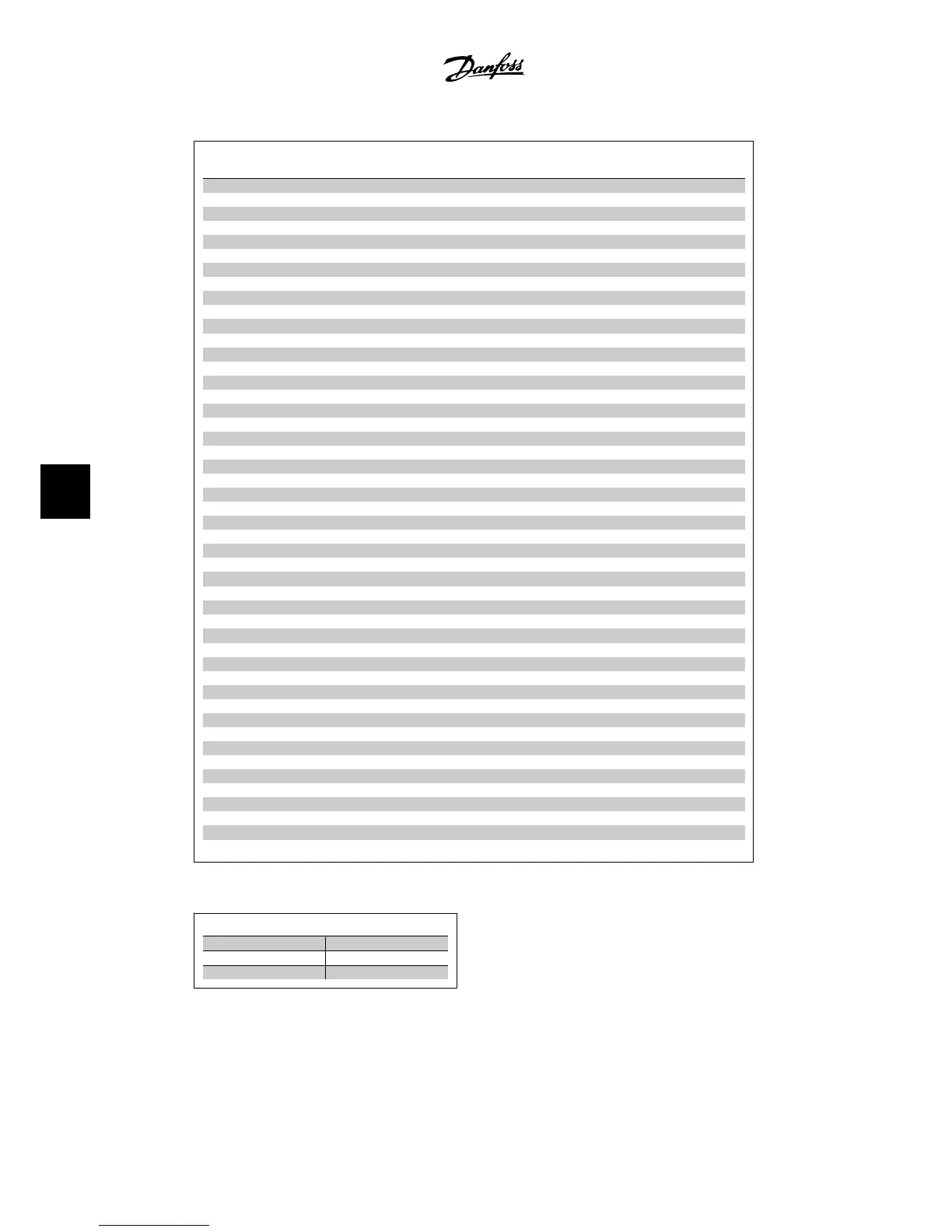
No. Description Warn-
ing
Alarm/Trip Alarm/Trip Lock Parameter Refer-
ence
1 10 Volts low X
2 Live zero error (X) (X) 6-01
3 No motor (X) 1-80
4 Line phase loss (X) (X) (X) 14-12
5 DC link voltage high X
6 DC link voltage low X
7 DC overvoltage X X
8 DC undervoltage X X
9 Inverter overloaded X X
10 Motor ETR overtemperature (X) (X) 1-90
11 Motor thermistor overtemperature (X) (X) 1-90
12 Torque limit X X
13 Overcurrent X X X
14 Ground fault X X X
15 Hardware mismatch X X
16 Short Circuit X X
17 Control word timeout (X) (X) 8-04
25 Brake resistor short-circuited X
26 Brake resistor power limit (X) (X) 2-13
27 Brake chopper short-circuited X X
28 Brake check (X) (X) 2-15
29 Power board overtemp. X X X
30 Motor phase U missing (X) (X) (X) 4-58
31 Motor phase V missing (X) (X) (X) 4-58
32 Motor phase W missing (X) (X) (X) 4-58
33 Soft-charge fault X X
34 Serial communication bus fault X X
38 Internal fault X X
47 24 V supply low X X X
48 1.8 V supply low X X
50 AMA calibration failed X
51 AMA check U
nom
and I
nom
X
52 AMA low I
nom
X
53 AMA motor too big X
54 AMA motor too small X
55 AMA parameter out of range X
56 AMA interrupted by user X
57 AMA timeout X
58 AMA internal fault X X
59 Current limit X
61 Tracking Error (X) (X) 4-30
62 Output Frequency at Maximum Limit X
64 Voltage Limit X
65 Control Board Overtemperature X X X
66 Heatsink Temperature Low X
67 Option Configuration Has Changed X
68 Safe Stop Activated X
80 Drive Initialized to Default Value X
Table 7.1: Alarm/Warning code list
(X) Dependent on parameter
LED indication
Warning yellow
Alarm flashing red
Trip-locked yellow and red
7. Troubleshooting VLT
®
HVAC Drive Instruction Manual
132
MG.11.A4.22 - VLT
®
is a registered Danfoss trademark
7

 Loading...


